Radio Transmitter

For your comments, suggestions, or your looking for a circuit or design, or a electronics designer, please send you Inquiries to pcb1001@gmail.com. We are happy to help and attend to your concerns.
Showing posts with label Amplifier. Show all posts

Saturday, June 13, 2009

LOW-COST HEARING AID

Commercially available hearing aids are quite costly. Here is an inexpensive hearing aid circuit that uses just four transistors and a few passive components. On moving power switch S to ‘on’ position, the condenser microphone detects the sound signal, which is amplified by transistors T1 and T2. Now the amplified signal passes through coupling capacitor C3 to the base of transistor T3. The signal is further amplified by pnp transistor T4 to drive a low impedance earphone. bg8j9xp2ym


Capacitors C4 and C5 are the power supply decoupling capacitors. The circuit can be easily assembled on a small, general-purpose PCB or a Vero board. It operates off a 3V DC supply. For this, you may use two small 1.5V cells. Keep switch S to ‘off’ state when the circuit is not in use. To increase the sensitivity of the condenser microphone, house it inside a small tube. This circuit costs around Rs 65.

Friday, June 5, 2009

Active Antenna HF/VHF/UHF, 3-3000MHz

If you have a shortwave or high-frequency receiver or scanner that is struggling to capture signals with a short, whip antenna, and you'd like the kind of performance that a 60-foot 'longwire' antenna can provide but lack the space to put one up, consider building the AA-7 HF/VHF/UHF Active Antenna described in this article. The AA-7 is a relatively simple antenna that is designed to amplify signals from 3 to 3000 MegaHertz, including three recognized ranges: 3-30Mhz high-frequency (HF) signals; 3-300Mhz very-high frequency (VHF) signals; 300-3000MHz ultra-high (UHF) frequency signals. Those bands are typically occupied by shortwave, ham, government, and commercial radio signals.


Active Antennas:

In its simplest form, an active antenna uses a small whip antenna that feeds incoming RF to a pre-amplifier, whose output is then connected to the antenna input of a receiver. Unless specifically designed otherwise, all active antennas are intended for receive-only operation, and thus should not be used with transceivers; transmitting into an active antenna will probably destroy its active components. A well designed broadband active antenna consider field strength of the desired signal (measured in microvolts per meter of antenna length), atmospheric and other noise, diameter of the antenna, radiation resistance, and antenna reactance at various frequencies, plus the efficiency and noise figure of the amplifier circuit itself.


Circuit Description:


Figure shows the schematic diagram of the AA-7, which contains only two active elements; Q1 (an MFE201 N-Channel dual-gate MOSFET) and Q2 (a 2SC2570 NPN VHF silicon transistor). Those transistors provide the basis of two independent, switchable RF pre-amplifiers. Two double-pole double-throw (DPDT) switches play a major role in this operation of the AA-7. Switch S1 is used to select one of the two pre-amplifier circuits (either HF or VHF/UHF). Switch 2 is used to turn off the power to the circuit, while coupling the incoming RF directly to the input of the receiver. That gives the receiver non-amplified access to the auxiliary antenna jack, at J1, as well as the on-board telescoping whip antenna. With switch S2 in its power-on position, the input and output jacks are disconnected and B1 (a 9 volt battery) is connected to the circuit. With switch S1 in the position shown in the schematic, incoming RF is directed to the HF pre-amp circuit built around Q1 (an MFE201 N-Channel dual-gate MOSFET). The HF pre-amp operates with an exceptionally low noise level, and is ideal for copying weak CW and singe-side band signals. When S1 is switched to the other position, the captured signal is coupled to the VHF/UHF pre-amp built around Q2 (a 2SC2570 NPN VHF silicon transistor), which has excellent VHF through microwave characteristics. With the on-board whip antenna adjustable to resonance through much of the VHF-UHF region (length in feet = 234 divide by the frequency in MHz), the VHF/UHF mode is ideal for indoor and portable use with VHF scanners and other receivers. Either mode can be used when tuning 3-30 MHz HF signals. The VHF/UHF pre-amp offers higher gain than the HF pre-amp, but also has a higher noise level. You can easily choose either amplifier for copying any signal; of interest--just try both positions. The RF gain control (R5) can be used to trim the output of either amplifier.

Caution: The AA-7 is not intended for transmitting operation (be it Ham, Maritime, or CB); if it is used with a transceiver of any kind, make sure it is not possible to transmit by accidentally pressing a mike button or CW keyer. Transmitting RF into the AA-7 is likely to ruin one or both of the transistors in the circuit.

Parts List and other components:

Semiconductors:

Q1 = MFE201, SK3991, or NTE454. N-Channel, dual-gate MOSFET, TO-72 (see text)
Q2 = 2SC2570, NTE107. Silicon RF IF/Amp, NPN transistor (see text)
Note: If you use the NTE107 as a replacement, make sure to insert it correctly
into the pcb. The orientation is different than as shown on the parts layout
diagram. (e-c-b seen front view for NTE107). See this Data Sheet

Resistors:

All Resistors are 5%, 1/4-watt
R1 = 1 Mega Ohm
R2 = 220K
R3,R6 = 100K
R4 = 100 ohm
R5 = 10K potentiometer (pc mount)
Capacitors:

C1,C2,C5,C6 = 0.01uF, ceramic disc
C3 = 100pF ceramic disc
C4 = 4.7 to 10uF, 16WVDC, radial lead electrolytic

Additional Parts & Materials:

B1 = 9-volt alkaline battery
S1,S2 = DPDT PC mount pushbutton switch
J1,J2 = PC mount RCA jack
ANT1 = Telescoping whip antenna (screw mount)
MISC = PCB materials, enclosure, enclosure, battery holder and connector,
wire, solder, etc.

Wednesday, June 3, 2009

Precision Metronome & Pitch generator

Precision Frequency generator 1 to 999 Hz
Precision Metronome 1 to 999 beats per minute

Circuit Diagram:


Parts:
R1__________1M 1/4W Resistor
R2_________22K 1/4W Resistor
R3__________6K8 1/4W Resistor
R4__________4K7 1/4W Resistor
R5_________47K 1/4W Resistor
R6________100K 1/4W Resistor
R7_________39K 1/4W Resistor
R8_________12K 1/4W Resistor
C1_________47pF 63V Ceramic Capacitor
C2_______2-22pF 63V Ceramic Trimmer
C3________470pF 63V Ceramic Capacitor
C4_________10pF 63V Ceramic Capacitor
C5________100nF 63V Polyester Capacitor
C6________220nF 63V Polyester Capacitor
C7_________22µF 25V Electrolytic Capacitor
D1-D15___1N4148 75V 150mA Diodes
IC1________4060 14 stage ripple counter and oscillator IC
IC2________4082 Dual 4 input AND gate IC
IC3________4520 Dual binary up-counter IC
IC4________4518 Dual BCD up-counter IC
IC5________4046 Micropower Phase-locked Loop IC
IC6________4040 12 stage ripple counter IC
Q1________BC337 45V 800mA NPN Transistor
XTAL______2.4576 MHz Miniature quartz crystal
SW1__________BCD Miniature Thumbwheel Switch (units)
SW2__________BCD Miniature Thumbwheel Switch (tens)
SW3__________BCD Miniature Thumbwheel Switch (hundreds)
SW4_________SPST Slider Switch (On-off)
SW5_________SPDT Slider Switch (Metronome-Pitch)
SPKR_______8 Ohm, 50 mm. Loudspeaker
B1_________9V PP3 Battery
Clip for 9V PP3 Battery

Circuit operation:

CMos IC1 and IC2B quad AND gate form a 2.4576 MHz crystal oscillator plus a 2400 times divider. IC3A provides further division by 16, delivering a 64 Hz stable frequency square wave. This frequency is multiplied (by means of Phase Locked Loop IC5, double decade divider IC4 and IC3B 4 bit binary divider) by the number set by three miniature BCD thumbwheel switches SW1, SW2 and SW3: units, tens and hundreds respectively.

Connecting, by means of SW5, Q1 base to pin 2 of IC6, we obtain (after a 64 times division) the same frequency set by thumbwheel switches with quartz precision, and no need for a scale indicator.

Volume regulation of the pitch generator is obtained trimming resistor R5. In the same way, with SW5 set to metronome, the small speaker reproduces the frequency set by thumbwheel switches but divided by 3840, thus obtaining beats per minute ratio.

Fuzz-box

All-FET design Valve-like distortion behavior


Parts:

P1______________10K Log. Potentiometer
R1_______________1M 1/4W Resistor
R2_______________3K3 1/4W Resistor
R3_______________2K2 1/4W Resistor
R4_______________5K 1/2W Trimmer (Cermet)
R5_____________100K 1/4W Resistor
C1,C4__________100nF 63V Polyester Capacitors
C2_____________100pF 63V Ceramic Capacitor
C3,C5___________22µF 25V Electrolytic Capacitors
Q1,Q2,Q3______2N3819 General-purpose N-Channel FETs
J1,J2__________6.3mm Mono Jack sockets
SW1_____________DPDT Toggle - Slider or Pedal Switch
SW2_____________SPST Toggle or Slider Switch
B1________________9V PP3 Battery
Clip for PP3 Battery

Comments:

This circuit was designed to obtain a valve-like distorted sound from an electric guitar or other musical instrument.

For this purpose a very high gain, three-FET amplifier circuit, was used. The output square wave shows marked rounded corners, typical of valve-circuits when driven into saturation.

Therefore, the distorted sound obtained from such a device has a peculiar tone, much loved by most leading guitarists.

Technical data:

  1. Input sensitivity: 30mV RMS.
  2. Output square wave: 6V peak-to-peak max.
  3. Total current drawing: about 1mA.

Circuit set-up using oscilloscope and sine wave generator:
Connect a 1KHz sine wave generator to J1 and the oscilloscope to J2.
Adjust R4 until the output square wave shows equal mark-space ratio.

"By ear"

circuit set-up:

Connect a musical instrument to J1 and an amplifier to J2.
Carefully adjust R4 in order to obtain as maximum output sound intensity as possible.

Tuesday, April 28, 2009

High Gain Amplifier

The amp is based on the High Gain PCB, so uses a pair of LM3876 (or LM3886) power opamps, run from a ±35V supply. I used a cut-down P88 preamp PCB because I only wanted one preamplifier stage, but the entire board can also be used. Alternatively, the P19 amp can be run at higher gain than normal, alleviating the need for a preamp at all. The down side of this is that the noise level will be higher, and background noise may be audible with efficient speakers and/ or very quiet surroundings.


The internal layout can be seen best in Figures 2 and 3. The main heatsink runs down the middle of the amp, and it separates the input and output stages. The material is 10mm thick aluminium, 45mm high and 180mm long. Because this is a prototype of the chassis assembly, there are several things that I would do differently if I build another. The chassis is more complex than it should be, and there are several opportunities for simplification. These became obvious after the basic chassis was well underway (naturally), and there were holes that I couldn't 'undrill' to simplify construction. Such is life.


The front top view shows the general layout of the amp's internals. On the left is the sheet aluminium clamp that holds the capacitors in place, and against the central heatsink section is the P19 amp board. On the other side of the heatsink is the input selector switch and then the ½ P88 board.

Along the rear (from left to right) is the DC connector, speaker outputs and inputs. As it turns out, 4 inputs is enough for my application, and had I restricted it to that the shield between the last set of inputs and the speaker connectors would not have been needed.

The DC connector, speaker connectors and input RCA sockets are all mounted on blank fibreglass PCB material to insulate them from the chassis. Where needed, the copper was removed to create a rudimentary PCB pattern - this is evident on the DC and speaker panels. The boards were 'etched' using a rotary tool (Dremmel or similar). Although the resolution and accuracy are not good enough for an amplifier, this method works very well for such applications.


The back view shows the vent slots along the top, and you can see that the RCA connectors do not contact the chassis. Naturally, the speaker terminals are insulated. The DC connector is clearly visible on the right. It is a lot easier to simply make the back panel a little shorter than the other panels than it is to cut slots as shown. Even with a milling machine, these are somewhat tedious to do, and it is difficult to get perfect alignment without proper jigs. The hole for the DC plug and socket is relatively easily made using a drill and square file. The switch hole will require some fairly tedious filing if you use a rectangular switch as shown, however you can use any switch at all, because it only has to switch 9V AC.

Again, the slots look cool, but a series of holes will work just as well. There are a number of other refinements as well, and these are listed in the construction section below.

The Electronics

As noted above, the electronics are based on two existing projects - P19 stereo 50W amplifier, and P88 high quality preamp. The schematic is shown below (one channel only), and the P88 only uses the second half of the PCB. The P19 power amp is constructed normally, and there are no changes from the published project.

The inputs can be designated with whatever you want, and you can add more if desired (within the limits of the rear panel real estate). It is important that the gain of the preamp section is kept low enough to ensure that none of your inputs will clip the opamp. Assuming that CD/ DVD players are capable of about 2V, this means that the gain must be kept below 6.5 (16dB). This is not a problem unless you change the values of R7A, B and C, since the maximum gain is limited to about 9.5dB with the values shown.

The caps before and after the volume control can be bypassed completely (using wire links), but I do not recommend that you do so. If there is DC across the pot,it will become noisy and scratchy after a while. Even small amounts of DC can cause problems.

Power Supply Module

The power supply I used is probably overkill, but I simply used parts I had on hand. The schematic is shown below. Although I used zeners for the opamp supply as shown, some constructors are bound to be uncomfortable with such a simple arrangement. The P05 board can be used to provide full regulation, but with only one dual opamp, I'm not sure it is warranted.
A photo of the cpmplete module is shown below. The soft start isn't really needed with a 160VA transformer, but it does no harm, and allows remote low voltage switching. Since this was a requirement (the connectors are illegal for use with hazardous voltages), it was a small price to pay. Although the transformer is happy without the soft start, there is a total of 20,000uF on each supply rail, and this would place great stress on the bridge rectifier.


The two 2.2k 1W resistors across the filter caps in the supply box ensure that the caps will discharge even if the amplifier is not connected. They are not strictly needed, but are recommended to prevent nasty sparks is the amp is connected while the caps are still charged. Large electros can easily maintain a respectable charge for many hours.

The power supply is conventional in almost all respects. I used a 160VA transformer, a 400V 35A bridge rectifier, and a total of 20,000uF per supply rail - 4 x 10,000uF caps in all. When the connecting cable resistance is added in, there is almost no ripple at all at the amplifier, even with both channels at full power. The cable resistance aids filtering, but at the expense of slightly reduced maximum continuous power. I obtained over 40W per channel with both channels driven into an 8 ohm load, and peak short term power is over 60W / channel.

You can use less capacitance of course, but with some increase in ripple and (perhaps) noise. For an amp of this nature, I expect that few constructors will want to use less than about 4 x 4,700uFcaps. Additional capacitance can also be used in parallel with the zener diodes, but 100uF 16V caps fit the P88 board easiliy. There is nothing to suggest that more capacitance will serve any purpose.

Since the amplifier is absolutely dead quiet even at full volume with unterminated inputs, there is nothing one can do to make it any better. Placing one's ear right next to the speaker (one of average sensitivity), circuit noise is just audible. There is no hum at all.

Sunday, April 26, 2009

Super Amplifiers 300W Output Power

The circuit described on this page is a modification of the original Double Barreled Amplifier. The circuit has been simplified somewhat. The circuit board layout is smaller and much more compact. The driver transistors now mount on the circuit board instead of on external heat sinks. And the circuit has the feedforward compensation that I describe for the Low TIM Amplifier.

The original circuit board for one channel had eight 5-watt resistors on it, one in series with the emitter of each output transistor. On the new layout, four of these have been moved to the heat sink channel where they solder between pins of the transistor sockets. This change not only helps make the circuit board smaller, but it eliminates eight wires between the heat sink and the circuit board. One of the figures below illustrates how these resistors are installed in the heat sink channel.


If you build this amplifier, you must keep the wiring between the heat sinks and the circuit boards as short as possible if you don't want oscillation problems.

When you test the circuit boards before connecting the power transistors, temporarily connect a 10 ohm resistor in series with a 0.1 ufd capacitor from the loudspeaker output to the power supply ground.

The Circuit Boards


We do not have circuit boards for the Double Barrelled Amplifier. If you wish to build it, you must make your own. Two drawings show the parts layout on the board, one with circuit traces and one without. These are scaled by a factor of 1.5. The other shows the circuit traces only. All layout views are from the component side of the board. You must flip the layout for the foil traces over to obtain the solder side view. The circuit board measures 4 inches by 6 inches. To my knowledge, there are no errors in the layout. If you decide to use it, you should carefully check it for errors because I could have easily made a mistake.


We do not recommend that you make the circuit boards unless you have experience in doing it. A source of materials for making your own printed circuits can be found here. I have been told that their "Press and Peel Blue" product (not the wet stuff they sell) can be used to successfully make boards with traces as narrow as 0.01 inch. The smallest traces on the amplifier layout are 0.03 inch wide. The PnP Blue product is basically a transfer medium that allows you to transfer the toner image from a laser printer directly onto bare copper clad board and then etch it in FeCl3 (ferric chloride).


After you etch the board, the copper should be cleaned with steel wool, lightly coated with solder flux, and then "tinned" with a soldering iron and rosin core solder. Do not use a commercial tinning solution that you dip the board into. It is almost impossible to solder a board that is tinned with one of these products because they corrode very quickly. When you drill the board, you should use the correct size drill bit for the pads. The hole diameters I recommend are: small pads - 0.032 inch, medium pads - 0.040 inch, large pads - 0.059 inch, mounting holes - 0.125 inch. If you do not use a sharp drill bit, you can pull the pads off the board when you drill it.


Circuit Description

If you compare the Double Barreled circuit to the Low TIM circuit, you will see a lot of similarity between the two. Indeed, there is a Low TIM Amplifier embedded in the Double Barreled Amplifier. The major difference between the two is that transistors are added in series with those in the Low TIM circuit to form the Double Barreled circuit. By doing this, the voltage across the transistors is decreased so that the power supply voltage can be increased for higher output power.

Basically, the circuit description for the Low TIM Amplifier also applies to the Double Barreled Amplifier. The major difference between the two is the addition of transistors Q22 through Q31. Q22 is connected as a common base stage at the output of Q12. The two transistors form a cascode stage. The base of Q22 connects to the junction of R52 and R54. These two resistors are equal and are connected as a voltage divider between the loudspeaker output and the positive rail. This forces the base voltage of Q22 to float half way between the loudspeaker output voltage and the positive power supply rail. Similarly, Q13 and Q23 form a cascode stage. R53 and R55 force the base of Q23 to float half way between the loudspeaker output voltage and the negative power supply rail. The addition of Q22 and Q23 cause the collector to emitter voltages of Q12 and Q13 to be approximately one-half of what the voltages would be without Q22 and Q23.

Transistors Q24 and Q25 connect in series with the pre-driver transistors Q14 and Q15. The base of Q24 floats half way between the output voltage and the positive rail. The base of Q25 floats half way between the output voltage and the negative rail. The addition of Q24 and Q25 cause the voltages across Q14 and Q15 to be approximately one-half of what they would be without Q24 and Q25. Similarly, transistors Q26 through Q31 cause the voltages across Q16 through Q21 to be approximately one-half of what they would be without Q26 through Q31. By connecting the transistors in series in this way, the rail voltages can be increased for higher output power.

The basic construction details of the Low TIM Amplifier also apply to the Double Barreled Amplifier. There are two short circuit jumper wires that must be soldered on the circuit board. These are marked with a J on the layout. In addition, you must solder a short circuit jumper in place of C6B if you use a non-polar capacitor for C6A. This is explained in the parts list for the Low TIM Amplifier. Because there are eight output transistors, two main heat sinks per channel are required. Q18, Q20, Q28, and Q30 should be mounted on one and Q19, Q21, Q29, and Q31 on the other. Resistors R61 through R64 and wires connecting the collectors of Q18 and Q20 and the collectors of Q19 and Q21 mount on the heat sinks. These connect between lugs on the transistor sockets. The four bias diodes D1 through D4 can be mounted on either heat sink. It is not necessary to divide the diodes between the two heat sinks because both heat sinks will operate at the same temperature. I recommend setting the voltage across Q7, i.e. the voltage between the collectors of Q22 and Q23, so that that amplifier is biased at 120 mA. This will give the same quiescent power dissipation per heat sink as in the Low TIM Amplifier.

Testing the Circuit Boards

After you solder the parts to the circuit board, it is tested using the same procedure specified for the Low TIM circuit board. First, you must solder the short circuit jumper across Q7 and you must solder the 100 ohm 1/4 W resistors from the loudspeaker output to the emitters of Q16 and Q17. If you don't have a bench power supply that puts out plus and minus 85 to 93 V dc, you can test the circuit board at a lower voltage. I would prefer test voltages of at least plus and minus 50 V dc. An option is to connect bench power supplies in series to obtain the plus and minus 85 to 93 V dc. I have routinely connected two 40 V Hewlett Packard power supplies in series with the positive and negative outputs of a Hewlett Packard 50 V dual power supply, and I have never had any problems. To protect the circuit boards, you might want to put a 100 ohm 1/4 W resistor in series with the plus and minus power supply leads for the tests. The current drawn by the circuit should be low enough so that the voltage drop across these resistors is less than 1 V if nothing is wrong on the circuit board. There are 2 ground wires from the circuit board. Both must be connected when testing the boards.

I can't stress how important it is to be careful in testing a circuit board. Even simple errors can cause the loss of many expensive transistors. I always use current limited bench power supplies to test a circuit board before and after connecting the power transistors. I also bias an amplifier using current limited power supplies in place of the amplifier power supply. When I initially power up an amplifier with its own power supply, I always use a Variac variable transformer to slowly increase the ac input voltage from 0 to 120 V rms while observing the amplifier output on an oscilloscope with a sine wave input signal. If I see anything wrong on the oscilloscope, I turn the Variac to zero and try to diagnose the problem using the bench power supply. I never use a load on the amplifier for these tests.

Parts List

With the following exceptions, the parts for the Double Barreled Amplifier are the same as for the Low TIM Amplifier.

Capacitors

  • C10, C11 - 15 pF mica
  • C13, C14 - 100 uFd 100 V radial electrolytic
  • C21, C22 - 47 uFd 100 V radial electrolytic
  • C26, C27 - 270 pF mica
  • C28 - 0.01 uFd 250 V film

Transistors

  • Q1, Q2, Q5, Q7, Q9, Q10 - MPS8099 or MPSA06
  • Q3, Q4, Q6, Q8, Q11 - MPS8599 or MPSA56
  • Q23, Q24 - 2N3439
  • Q22, Q25 - 2N5415
  • Q26 - MJE15030
  • Q27 - MJE15031
  • Q28, Q30 - MJ15003
  • Q29, Q31 - MJ15004

Diodes

  • D5, D6 - 1N4934 fast recovery rectifier
  • D13 through D16 - 1N5250B 20 volt zener diode

Resistors

  • R13, R14 - 5.6 kohm 1 watt (This value is for 85 V power supplies. For other power supply voltages, the formula is on the Parts List page for the Leach Amp.)
  • R28, R29 - 200 ohm 1/4 watt
  • R30, R31 - 3.9 kohm 1 watt
  • R37 through R40 - 470 ohm 1/4 watt
  • R41 through R44 - 10 ohm 1/2 watt (changed 6/27/00)
  • R52 through R55 - 6.2 kohm 1 watt
  • R56 through R59 - 10 ohm 1/2 watt (changed 6/27/00)
  • R60 - 39 ohm 1/4 watt
  • R61 through R64 - 0.33 ohm 5 watt. These 4 resistors are mounted on the heat sinks between solder lugs on the power transistor sockets. The wires that connect the collectors of Q18 and Q20 and the collectors of Q19 and Q21 are also soldered between the lugs on the sockets. Keep all leads as short as possible and use insulation stripped from hookup wire around the bare leads of the resistors.
  • R65, R66 - 300 ohm 1/4 watt

Heat Sinks

  • Double the number of heat sinks required for the Low TIM Amplifier.

Power Supply Components

The power supply circuit diagram is the same as for the Low TIM Amplifier. The parts are the same with the following exceptions.

  • T1 - The transformer should have either a center tapped secondary or two separate secondary windings which can be wired in series. With 120 V ac rms applied to the primary, the no load secondary voltage should be 120 to 130 V ac rms for a center tapped secondary or 60+60 (60x2) to 65+65 (65x2) V ac rms for two secondary windings. This should give a no load amplifier power supply voltage of plus and minus 85 to 93 V dc. Some transformers are rated at 115 V ac rms on the primary. With 120 V ac rms applied, the secondary voltage will be greater by a factor 120/115. If the transformer is rated at full load, its no load voltage will be 15% to 20% higher. I would recommend a transformer current rating of at least 6 A. The transformer I used in each of my two original Double Barreled Amplifiers was the Signal 230-6. It had two center tapped 115 V 6 A secondaries which I wired in parallel to obtain a secondary rating of 115 V at 12 A. The primary had three voltage taps: 105 V, 115 V, and 125 V. I wired the AC line input to the 115 V tap. With 120 V AC applied to the 115 V tap, I got plus and minus 85 V DC on the power supplies and 270 W into an 8 ohm load. If I had used the 105 V primary taps, the power supply voltage would have increased to about 93 V and the amplifiers would have put out over 300 W. The Signal transformer was definately an overkill. It weighed 38 pounds. But it would really kick you know what. To my knowledge, this transformer now is available only by special order.
  • C1P, C2P - I used two Mallory CG832U100G1 8,600 uFd 100 V capacitors in parallel for each of these so that I had 34,400 uFd total in each of my two amplifiers. This was probably an overkill. The energy stored in the eight apacitors was about 250 joules. This is enough energy to lift a 25 pound dog over 7 feet off the floor. For C1P and C2P, I would recommend at least 10,000 uFd total for each. The voltage rating should be 100 V or greater.

New Vacuum Tube Amplifier


Features

  • Output: 4-6550's in triode-mode class AB2 push-pull parallel. About 80 watts RMS per channel.
  • No global negative feedback. Several local loops with limited negative feedback.
  • Ultra-wide bandwidth Plitron toroidal output transformer.
  • Servo to maintain precise dc-balance in the output circuit.
  • MOSFET-regulated power supplies. Relative rather than absolute voltage reference.
  • Designed using extensive PSpice computer simulation.
  • Constructed as a pair of monoblocks.

Schematic diagram


Notes on the schematic diagram

  • The power supply has been simplified-- Power transformers and rectifiers have been omitted and some parts have been omitted from the MOSFET voltage regulator circuits: 1N5242 zener diodes between the source and gate and 10k resistors in series with the gate. These parts serve as protection in case of accidental short circuits, but don't affect the operating point. The full power supply schematic is shown below.
  • 6SN7's are used instead of 12AU7's for the driver tubes. They have the same plate characteristics, but they have higher maximum plate voltage (450 vs. 330 V) and greater plate dissipation (3.75 vs. 2.75 W per section). Think of the octal-based 6SN7 as a 12AU7 on steroids.
  • The NODESET blocks (lower right) initialize dc levels in the bias servo so the simulation runs properly. They don't exist as physical entities.
  • All resistors are 1/2 watt unless noted, and with the following exceptions. R3P, R4P and R5C through R8C (68K) are 2W. R9C through R12C (20 ohm) are 1W: I used 2-10 ohm resistors in series to make them. R9S through R12S (200 ohms) are 2W.
  • Capacitor voltage ratings: It never hurts to go over the minimum, though the capacitors will be larger and may cost more. I often use caps with higher voltage ratings because I have them on hand or found them at a good price in an electronics surplus shop. Here are some minimum ratings: C1G: 100V. C2G: 400V (600V would be better; necessary without the time delay); C3G and C4G: 400V (600V would be better); C3M and C4M: 400V; C5G through C8G: 600V; CBS2, CBS4, CBS6 and CBX1 through CBX3: 100V. The voltage ratings of many of the power supply capacitors are shown on the circuit board wiring diagrams, below.
  • Some of the feedback connections may be a little hard to trace. ORN goes between the 20 ohm output transformer secondary feedback winding and R3F near TU3. Similarly, VLT goes to R4F near TU4. BLU and BLK on the output transformer secondary speaker winding go to the output tube cathode circuits.
  • RLS (5 ohms) is a simulated speaker load.
  • CRF: All three nodes are connected together.
  • BRN and VIO are not used. They are the ultra-linear taps. In the original version of TENA there was a switch to select output tube screen grid connections between BRN and VIO (UL mode) and GRN and YEL (triode mode).

Input stage/phase inverter

Input stage TU1 is a simple voltage gain stage with local negative feedback, derived from the R1B, R1C voltage divider. It is capacitively coupled to split load phase inverter TU2. The capacitor has an unusually low value-- 0.01 µF-- because TU2 has an exceptionally high input impedance-- several Megohms. The advantage of capacitive coupling is that it allows the voltage level in TU2 to be set for maximum output and it allows the ac current in TU2 to be precisely equal to, but 180 degrees out of phase with, the current in TU1. The net ac current drawn by these two tubes from V+420 is therefore zero. This is an effective way of isolating the audio signal from the power supply, which doesn't need to supply ac current. In conventional designs ac signal often has to flow through electrolytic capacitors, which are grungy leaky devices with memory-- harmful to audio quality. I designed TENA to draw zero net ac current from all power supply outputs (easy to do in a push-pull design), at least up to the power level where one of the output tube pairs starts cutting off.

Toroidal output transformer

We chose the Plitron toroidal transformer because of its exceptional bandwidth: -3 dB at over 200 kHz, the result of high primary inductance (the good stuff) and low leakage inductance (the bad stuff-- kind of like HDL and LDL cholesterol)-- much better than can be achieved with a conventional EI transformer. High bandwidth is important because output transformers have an intrinsic second order rolloff, which can make them unstable in the presence of negative feedback unless careful phase compensation is applied (see Feedback and Fidelity). Phase compensation reduces the bandwidth, which is not a problem with the Plitron toroidal transformers. But this bandwidth comes at a price-- toroidal transformers are much less tolerant of dc-imbalance than EI transformers; they may saturate at dc imbalances as low as 8 mA. (I don't know the exact number; I never simulated it.) You would have to set the bias of each tube individually, and then you'd have to worry about how the tubes age. So I designed a bias servo circuit to maintain perfect dc-balance under all circumstances except outright tube failure.

The Plitron PAT 4006CFB 100 Watt toroidal output transformer is not currently listed on Plitron's website, but I've heard (June 2003) that it is available. Contact Norman Woo. The closest models are the 4006, which lacks the special feedback winding, and the 2100-CFB which has a higher primary impedance. The minimum feedback version of TENA (below) works with the 4006.

Bias servo and adjustment

The time-averaged (low pass filtered) dc current of an output tube operating in class AB fixed bias is relatively constant at low power levels but increases at high power levels. For this reason a fixed voltage cannot be used as a reference for biasing the output tubes. One tube (TU9, driven by TU5) operates at fixed bias, and its low pass filtered cathode voltage (CRF) is used as the reference for biasing the other tubes.

The bias servo is illustrated in the lower left of the schematic. It uses the LM324 quad op amp-- cheap but perfectly adequate. Inputs U1A, U1B and U1C of the LM324 compare cathode voltages 10C, 11C, and 12C with reference voltage CRF, which is the voltage on cathode 9C low pass filtered with RBS2 = 33k and CBS1 = 10µF ( located near U1B on the schematic). The LM324 outputs control the P-channel MOSFETs, each of which controls a voltage divider between VBB (-90V) and VOP (+12.5V) to deliver the appropriate bias voltage to the driver grid circuits (BIAS_6, BIAS_7, and BIAS_8). This measures between -45 and -50V in my amplifiers, which operate at 60 mA plate current. Audio purists please note: the servo operates at extremely low frequencies; the op amp and MOSFETs are well outside the audio signal path.

A single potentiometer, RB5 (in the VBB supply, bottom center), controls the bias current directly in TU9, and all the other tubes indirectly through the servo. Bias current may be measured across any of the 20 ohm resistors R9C-R12C as E/20. They should all be the same if the servo is working properly. 1 to 1.2 volts is a good nominal value, corresponding to 50 to 60 mA per tube (70 mA was used in the Dynaco Mark III). Increasing the current increases power consumption and reduces tube life and output power, but moves you closer to Class A (where both tubes always conduct).

Class AB2 output stage and drivers

Class AB2 differs from the more common class AB1 in that the output stage grid is driven positive-- it draws grid current-- at high power levels. Class AB2 has no advantage for output tubes operating in pentode mode and little advantage for ultra-linear mode. But it results in a huge power boost for output tubes operating in triode mode. You can get almost as much power out of class AB2 triodes as you can out of class AB1 pentodes.

If you try to do operate in class AB2 with conventional capacitive coupling, the coupling capacitor starts charging as soon as grid current is drawn. This drives the grid negative-- toward cutoff, and it recovers with the RC time constant of the coupling capacitor and grid resistor. To operate successfully in class AB2, the output stage must be either transformer or direct coupled. I chose direct coupling because interstage transformers are expensive and have limited bandwidth.

The direct coupled drivers are the source of much of TENA's complexity. Because the quiescent grid voltage of each output tube must be set individually to control its quiescent (dc) current, one driver tube (TU5-TU8) is required for each output tube (TU9-TU12). Cathode followers (CF's) were chosen because they have low output impedance and can source the needed output tube grid current. The cathodes have to be somewhere near -50V to properly bias the output tubes. This means the CF must be driven by voltages outside the range of conventional power supplies, hence the need for VDR- and VDR+: the price of perfection. In reviewing the design I find that the driver tubes may be operating a little too conservatively-- dissipating only 0.78 W (of a 6SN7 maximum of 3.75 W). I've discussed driver dissipation under PSpice output, below. I may increase VDR+ from 205 to around 250 V by increasing RD1 from 470k to 680k. This would reduce the power dissipation in MOSFET MD1.

Output tube grid stop resistors R9G-R12G play an important role in TENA's soft clipping. When power levels become high enough level for grid current to be drawn, a voltage drop across these resistors gradually limits the plate current. Soft clipping consists of low order harmonics which have much less adverse effect on sound quality that the high order harmonics characteristic of abrupt clipping. But total harmonic distortion for soft clipping amplifiers tends to be higher. Yes, lower harmonic distortion doesn't mean better sound. See "The great harmonic distortion scam" in Feedback and Fidelity. TENA oscillated when the grid stop resistors were removed. This was the only performance feature PSpice didn't catch. The reason is that the output transformer model is somewhat simplified-- it's extremely difficult to model its distributed capacitance.

Power supplies

The time delay circuit (U3 (the 555B chip), Q1, Relay_SPDT_nb, RT1, CT1, CT2, RT3, D1, RV1, and RT4) has apparently never been implemented. RT4 should be replaced by a straight wire; VBIN is connected directly to NTC (negative temperature coefficient; 50 ohms cold; Mouser527-3504-50) thermistor RV10.

The precise values of most of the capacitors in the power supply, particularly CV1, CV2, CB1, CB2, CD1 and CD2, are not critical. In many cases they were determined by parts availability. If the values are 2 uF or under they are film capacitors. If they are over 2 uF they are electrolytics.

Depending how you count there are two (power transformers), four (rectifier circuits) or six (voltage levels). All use fast recovery rectifier diodes. All except VDR- are taken from the mighty Plitron 854710 toroidal power transformer, which I can't seem to find in their catalog. Toroidal power transformers perform well, but they have less of an advantage than toroidal output transformers-- you don't need wide bandwidth for 60 Hz. The CL80 inrush current limiter limits turn-on current in the tube filaments.

Saturday, April 18, 2009

DC Servo Amplifier with Negative Feedback

And negative feedback amplifier voltage than current negative feedback amplifier as excellent transient nonlinear distortion and intermodulation distortion characteristics, the frequency amplifier curve flat, high and low frequency response more exhibition wide; more important is that circuit Will load impedance into the feedback network, it can change the speakers of such fierce resistance to the load compensation, coupled with stable and reliable performance, than the negative feedback voltage amplifier has more advantages, the current negative feedback current amplifier is widely For the modern high-fidelity audio amplifier.


Circuit above is an excellent performance, improve the design of the fever-100 W × 2 DC Servo Amplifier current negative feedback stereo amplifier, formed by the two TDA7294, the frequency response of 10 Hz ~ 100kHz. The use of sophisticated audio Yun-double as the two-channel amplifier DC Servo Amplifier output. Speakers from the protection of ASIC μPC1237HA driver completed the relay switch-mute and amplifier output DC offset protection, and other speakers. When the AC power plug, the relay will be delayed for some time speakers access amplifier; disconnecting the AC power when, μPC1237HA detected exchange loss, immediately disconnect the speaker to relay, the amplifier is the complete elimination of the set, Shutting down the transition process the impact of noise on the speakers.

In actual use, taking into account the electricity grid fluctuations Rectifier amplifier output voltage ± Vs volatile, in order to avoid over-voltage and high temperature in the state of damage TDA7294 (Note pressure in the temperature of 25 ℃ under the conditions, if the temperature exceeds 25 ℃, TDA7294 the value will subsequently reduce the pressure), the exchange recommended power supply voltage transformer CT-AC26V × 2.

Motor current control circuit with external power transistors

The L165 is a monolithic integrated circuit in Pentawatt ® package, intended for use as power operational amplifier in a wide range of applications, including servo amplifiers and power supplies. The high gain and high output power capability provide superiore performance wherever an operational amplifier/power booster combination is required.


1.2W AUDIO AMPLIFIER

A very useful audio amp in an 8-pin DIL package. The IC features a very low minimum working supply voltage of 3V, low quiescent current, good ripple rejection, no crossover distortion and low power dissipation. Maximum supply voltages is 16 Volts into 16 Ohms speaker, 12Volts into 8 Ohms and 9Volts into 4 Ohms.


The TBA820M is a monolithic integrated audio amplifier in a 8 lead dual in-line plastic package. It is intended for use as low frequency class B power amplifier with wide range of supply voltage: 3 to 16V, in portable radios, cassette recorders and players etc. Main features are: minimum working supply voltage of 3V, low quiescent current, low number of external components, good ripple rejection, no cross-over distortion, low power dissipation.

Output power: Po = 2Wat 12V/8W, 1.6W at 9V/4W
and 1.2W at 9V/8W.

8 Watts Audio Amplifier

Nice small audio amplifier which use only few parts to give good quality sound. This amp can be used as a simple booster, the heart of a more complicated amplifier or used as a guitar amp. Although not perfect, this amplifier does have a wide frequency response, low harmonic distortion about 1.5%, and is capable of driving an 8 ohm speaker to output levels of around 8 watts with slightly higher distortion. Any power supply in the range 12 to 18 Volts DC may be used.

The TDA 2003 has improved performance with the same pin configuration as the TDA 2002.
The additional features of TDA 2002, very low number of external components, ease of assembly, space and cost saving, are maintained. The device provides a high output current capability (up to 3.5A) very low harmonic and cross-over distortion.

Completely safe operation is guaranteed due to protection against DC and AC short circuit between all pins and ground, thermal over-range, load dump voltage surge up to 40V and fortuitous open ground.

HI-FI CAR-RADIO Amplifier

Constraints of implementing high power solutions are the power dissipation and the size of the power supply. These are both due to the low efficiency of conventional AB class amplifier approaches.


Here above is described a circuit proposal for a high efficiency amplifier which can be adopted for both HI-FI and CAR-RADIO applications. The TDA7294 is a monolithic MOS power amplifier which can be operated at 80V supply voltage (100V with no signal applied) while delivering output currents up to ±10 A.

This allows the use of this device as a very high power amplifier (up to 180W as peak power with T.H.D.=10 % and Rl = 4 Ohm); the only drawback is the power dissipation, hardly manageable in the above power range. Figure 20 shows the power dissipation versus output power curve for a class AB amplifier, compared with a high efficiency one. In order to dimension the heatsink (and the power supply), a generally used average output power value is one tenth of the maximum output power at T.H.D.=10 %.

From figure below, where the maximum power is around 200 W, we get an average of 20 W, in this condition, for a class AB amplifier the average power dissipation is equal to 65 W. The typical junction-to-case thermal resistance of the TDA7294 is 1 oC/W (max= 1.5 oC/W). To avoid that, in worst case conditions, the chip temperature exceedes 150 oC, the thermal resistance of the heatsink must be 0.038 oC/W (@ max ambient temperature of 50 oC). As the above value is pratically unreachable; a high efficiency system is needed in those cases where the continuous RMS output power is higher than 50-60 W.

The TDA7294 was designed to work also in higher efficiency way. For this reason there are four power supply pins: two intended for the signal part and two for the power part. T1 and T2 are two power transistors that only operate when the output power reaches a certain threshold (e.g. 20 W). If the output power increases, these transistors are switched on during the portion of the signal where more output voltage swing is needed, thus ”bootstrapping” the power supply pins (#13 and #15). The current generators formed by T4, T7, zener diodes Z1,Z2 and resistors R7, R8 define the minimum drop across the power MOS transistors of the TDA7294. L1, L2, L3 and the snubbers C9, R1 and C10, R2 stabilize the loops formed by the ”bootstrap” circuits and the output stage of the TDA7294.


In figures above, the performances of the system in terms of distortion and output power at various frequencies (measured on PCB shown in fig. 19) are displayed. The output power that the TDA7294 in high efficiency application is able to supply at
Vs = +40V/+20V/-20V/ -40V; f =1 KHz is:
- Pout = 150 W@ T.H.D.=10 % with Rl= 4 Ohm
- Pout = 120 W@ ” = 1% ” ” ”
- Pout = 100 W@ ” =10% with Rl= 8 Ohm
- Pout = 80 W @ ” = 1% ” ” ”

Results from efficiency measurements (4 and 8 Ohm loads, Vs = ±40V) are shown by figures 23
and 24. We have 3 curves: total power dissipation, power dissipation of the TDA7294 and power dissipation of the darlingtons. By considering again a maximum average output power (music signal) of 20W, in case of the high efficiency application, the thermal resistance value needed from the heatsink is 2.2oC/W (Vs =±40 V and Rl= 4 Ohm).
All components (TDA7294 and power transistors T1 and T2) can be placed on a 1.5oC/W heatsink, with the power darlingtons electrically insulated from the heatsink. Since the total power dissipation is less than that of a usual class AB amplifier, additional cost savings can be obtained while optimizing the power supply, even with a high headroom.

Tuesday, April 7, 2009

Ultrasonic Pest Repellant

This electronic circuit is an ultrasonic pest repellant are repelled by variabble ultrasonic frequency in the range of 30 kHz to 50 kHz. Thus to increase the effectiveness, frequency of ultrasonic oscillator has to be continuously varied between certain limits.


By using this circuit design, frequency of emission of ultrasonic sound is continuously varied step-by-step automatically. Here five steps of variation are used but the same can be extended up to 10 steps, if desired. For each clock pulse output from op-amp IC1 CA3130 (which is wired here as a low-frequency square wave oscillator), the logic 1 output of IC2 CD4017 (which is a well-known decade counter) shifts from Q0 to Q4 (or Q0 to Q9).

Five presets VR2 through VR6 (one each connected at Q0 to Q4 output pins) are set for different values and connected to pin 7 of IC3 (NE555) electronically. VR1 is used to change clock pulse rate. IC3 is wired as an astable multivibrator operating at a frequency of nearly 80 kHz. Its output is not symmetrical. IC4 is CD4013, a D-type flip-flop which delivers symmetrical 40kHz signals at its Q and Q outputs which are amplified in push-pull mode by transistors T1, T2, T3 and T4 to drive a low-cost, high-frequency piezo tweeter.

For frequency adjustments, you may use an oscilloscope. It can be done by trial and error also if you do not have an oscilloscope. This pest repeller would prove to be much more effective than those published earlier because here ultrasonic frequency is automatically changed to cover different pests and the power output is also sufficiently high. If you want low-power output in 30-50 kHz ultrasonic frequency range then the crystal transducer may be directly connected across Q and Q outputs of IC4 (transistor amplifier is not necessary).

2-Way Electronic Crossover Network

The electronic crossover featured here is an 18dB / octave unit, and has the crossover frequency centred on 300Hz. The frequency may be changed by increasing (or decreasing) resistor / capacitor values.

Increasing capacitance or resistance - Reduces frequency
  • Doubling the capacitance or resistance halves the frequency
Reducing capacitance or resistance - Increases frequency
  • Halving the capacitance or resistance doubles the frequency

The values of resistance and capacitance (indicated with a * in the circuit diagram) in the filter are critical, and close tolerance components are mandatory. If you cannot obtain close tolerance capacitors, use a capacitance meter to select values within 5% of the indicated value. Use only 1% metal film resistors throughout. The 1uF coupling caps are not critical, and standard tolerance is Ok.


If the crossover frequency is changed, it is critical that the ratios of capacitor and resistor values are not varied. For example, if you wanted to halve the frequency, the resistors would become 22k and 102k (100k is only just acceptable. If the ratios are changed, the filter damping is also changed, and the behaviour at the crossover point will be unpredictable (causing a dip or peak in the frequency response).

The values you change to alter the crossover frequency are indicated with a * in the circuit diagram

Do not change the 10k resistors - they set the damping of the filter and strange happenings will befall s/he who fiddles indiscriminately.

the NE5532 Dual op-amp is used. This circuit can be operated from the same power supply as the Audio Preamp, featured elsewhere on these pages. Other dual opamps may also be used, depending on your preference.
The input is buffered by U1a (the second channel can use the other half of the op-amp), and fed to the two filter networks. Each filter is a 3rd order section, and has a gain of 2. The output of each section is fed (via a 1uF polyester capacitor) to the level control and output buffer stage.
In use, the output of the preamplifier is fed to the input of the crossover network, and the outputs are fed to their respective amplifiers. For more information on bi-amping, refer to the article "Bi-Amplification - Not quite magic (but close)" on these pages.

Be careful when adjusting the level controls, since it is easy to create a mismatch in levels between the amplifiers. I suggest that the controls be mounted on the rear panel, with their shafts cut off really short, and a slot cut into the end with a hacksaw. Once the adjustment is made, it should not require further changes in use. Make sure that the power amplifier volume controls (if fitted) are turned fully up, and try to set the crossover controls so somewhere between midway and 75%. This ensures plenty of scope for getting the levels right, and will ensure that the preamp settings are not radically different from their "pre-biamp" days.

Thursday, April 2, 2009

60W MosFet Audio Amplifier

High Quality, powerful unit: 90W into 4 Ohm load
Also suited as guitar or bass amplifier

To celebrate the hundredth design posted to this website, and to fulfil the requests of many correspondents wanting an amplifier more powerful than the 25W MosFet, a 60 - 90W High Quality power amplifier design is presented here. Circuit topology is about the same of the above mentioned amplifier, but the extremely rugged IRFP240 and IRFP9240 MosFet devices are used as the output pair, and well renowned high voltage Motorola's transistors are employed in the preceding stages.

The supply rails voltage was kept prudentially at the rather low value of + and - 40V. For those wishing to experiment, the supply rails voltage could be raised to + and - 50V maximum, allowing the amplifier to approach the 100W into 8 Ohm target: enjoy! A matching, discrete components, Modular Preamplifier design is available here: Modular Audio Preamplifier.


Parts:

  • R1______________47K 1/4W Resistor
  • R2_______________4K7 1/4W Resistor
  • R3______________22K 1/4W Resistor
  • R4_______________1K 1/4W Resistor
  • R5,R12,R13_____330R 1/4W Resistors
  • R6_______________1K5 1/4W Resistor
  • R7______________15K 1/4W Resistor
  • R8______________33K 1/4W Resistor
  • R9_____________150K 1/4W Resistor
  • R10____________500R 1/2W Trimmer Cermet
  • R11_____________39R 1/4W Resistor
  • R14,R15___________R33 2.5W Resistors
  • R16_____________10R 2.5W Resistor
  • R17_______________R22 5W Resistor (wirewound)
  • C1_____________470nF 63V Polyester Capacitor
  • C2_____________470pF 63V Polystyrene or ceramic Capacitor
  • C3______________47µF 63V Electrolytic Capacitor
  • C4,C8,C9,C11___100nF 63V Polyester Capacitors
  • C5______________10pF 63V Polystyrene or ceramic Capacitor
  • C6_______________1µF 63V Polyester Capacitor
  • C7,C10_________100µF 63V Electrolytic Capacitors
  • D1___________1N4002 100V 1A Diode
  • D2_____________5mm. Red LED
  • Q1,Q2,Q4_____MPSA43 200V 500mA NPN Transistors
  • Q3,Q5________BC546 65V 100mA NPN Transistors
  • Q6___________MJE340 200V 500mA NPN Transistor
  • Q7___________MJE350 200V 500mA PNP Transistor
  • Q8___________IRFP240 200V 20A N-Channel Hexfet Transistor
  • Q9___________IRFP9240 200V 12A P-Channel Hexfet Transistor

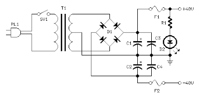
Power supply circuit diagram:

Parts:

  • R1_______________3K9 1W Resistor
  • C1,C2_________4700µF 63V Electrolytic Capacitors (See Notes)
  • C3,C4__________100nF 63V Polyester Capacitors
  • D1_____________400V 8A Diode bridge
  • D2_____________5mm. Red LED
  • F1,F2__________4A Fuses with sockets
  • T1_____________230V or 115V Primary, 30+30V Secondary 160VA Mains transformer
  • PL1____________Male Mains plug
  • SW1____________SPST Mains switch

Notes:
  • In the original circuit, a three-diode string was wired in series to R10. Two of these diodes are now replaced by a red LED in order to achieve improved quiescent current stability over a larger temperature range. Thanks to David Edwards of LedeAudio for this suggestion.
  • A small, U-shaped heatsink must be fitted to Q6 & Q7.
  • Q8 & Q9 must be mounted on large heatsinks.
  • Quiescent current can be measured by means of an Avo-meter wired in series to the positive supply rail and no input signal.
  • Set the Trimmer R10 to its minimum resistance.
  • Power-on the amplifier and adjust R10 to read a current drawing of about 120 - 130mA.
  • Wait about 15 minutes, watch if the current is varying and readjust if necessary.
  • The value suggested for C1 and C2 in the Power Supply Parts List is the minimum required for a mono amplifier. For optimum performance and in stereo configurations, this value should be increased: 10000µF is a good compromise.
  • A correct grounding is very important to eliminate hum and ground loops. Connect to the same point the ground sides of R1, R3, C2, C3 and C4 and the ground input wire. Connect R7 and C7 to C11 to output ground. Then connect separately the input and output grounds to the power supply ground.

Technical data:

Output power:
  • 60 Watt RMS @ 8 Ohm (1KHz sinewave) - 90W RMS @ 4 Ohm
Sensitivity:
  • 1V RMS input for 58W output
Frequency response:
  • 30Hz to 20KHz -1dB
Total harmonic distortion @ 1KHz:
  • 1W 0.003% 10W 0.006% 20W 0.01% 40W 0.013% 60W 0.018%
Total harmonic distortion @10KHz:
  • 1W 0.005% 10W 0.02% 20W 0.03% 40W 0.06% 60W 0.09%
  • Unconditionally stable on capacitive loads

10W Audio Amplifier with Bass-boost

High Quality, very simple design
No preamplifier required

This design is based on the 18 Watt Audio Amplifier, and was developed mainly to satisfy the requests of correspondents unable to locate the TLE2141C chip. It uses the widespread NE5532 Dual IC but, obviously, its power output will be comprised in the 9.5 - 11.5W range, as the supply rails cannot exceed ±18V.

As amplifiers of this kind are frequently used to drive small loudspeaker cabinets, the bass frequency range is rather sacrificed. Therefore a bass-boost control was inserted in the feedback loop of the amplifier, in order to overcome this problem without quality losses. The bass lift curve can reach a maximum of +16.4dB @ 50Hz. In any case, even when the bass control is rotated fully counterclockwise, the amplifier frequency response shows a gentle raising curve: +0.8dB @ 400Hz, +4.7dB @ 100Hz and +6dB @ 50Hz (referred to 1KHz).


Parts:

  • P1_________________22K Log.Potentiometer (Dual-gang for stereo)
  • P2________________100K Log.Potentiometer (Dual-gang for stereo)
  • R1________________820R 1/4W Resistor
  • R2,R4,R8____________4K7 1/4W Resistors
  • R3________________500R 1/2W Trimmer Cermet
  • R5_________________82K 1/4W Resistor
  • R6,R7______________47K 1/4W Resistors
  • R9_________________10R 1/2W Resistor
  • R10__________________R22 4W Resistor (wirewound)
  • C1,C8_____________470nF 63V Polyester Capacitor
  • C2,C5_____________100µF 25V Electrolytic Capacitors
  • C3,C4_____________470µF 25V Electrolytic Capacitors
  • C6_________________47pF 63V Ceramic or Polystyrene Capacitor
  • C7_________________10nF 63V Polyester Capacitor
  • C9________________100nF 63V Polyester Capacitor
  • D1______________1N4148 75V 150mA Diode
  • IC1_____________NE5532 Low noise Dual Op-amp
  • Q1_______________BC547B 45V 100mA NPN Transistor
  • Q2_______________BC557B 45V 100mA PNP Transistor
  • Q3_______________TIP42A 60V 6A PNP Transistor
  • Q4_______________TIP41A 60V 6A NPN Transistor
  • J1__________________RCA audio input socket
Power supply parts:

  • R11_________________1K5 1/4W Resistor
  • C10,C11__________4700µF 25V Electrolytic Capacitors
  • D2________________100V 4A Diode bridge
  • D3________________5mm. Red LED
  • T1________________220V Primary, 12 + 12V Secondary 24-30VA Mains transformer
  • PL1_______________Male Mains plug
  • SW1_______________SPST Mains switch
Notes:

  • Can be directly connected to CD players, tuners and tape recorders.
  • Schematic shows left channel only, but C3, C4, IC1 and the power supply are common to both channels.
  • Numbers in parentheses show IC1 right channel pin connections.
  • A log type for P2 will ensure a more linear regulation of bass-boost.
  • Do not exceed 18 + 18V supply.
  • Q3 and Q4 must be mounted on heatsink.
  • D1 must be in thermal contact with Q1.
  • Quiescent current (best measured with an Avo-meter in series with Q3 Emitter) is not critical.
  • Set the volume control to the minimum and R3 to its minimum resistance.
  • Power-on the circuit and adjust R3 to read a current drawing of about 20 to 25mA.
  • Wait about 15 minutes, watch if the current is varying and readjust if necessary.
  • A correct grounding is very important to eliminate hum and ground loops. Connect to the same point the ground sides of J1, P1, C2, C3 &C4. Connect C9 to the output ground.
  • Then connect separately the input and output grounds to the power supply ground.

Technical data:

Output power:
  • 10 Watt RMS into 8 Ohm (1KHz sinewave)
Sensitivity:
  • 115 to 180mV input for 10W output (depending on P2 control position)
Frequency response:
  • See Comments above
Total harmonic distortion @ 1KHz:
  • 0.1W 0.009% 1W 0.004% 10W 0.005%
Total harmonic distortion @ 100Hz:
  • 0.1W 0.009% 1W 0.007% 10W 0.012%
Total harmonic distortion @ 10KHz:
  • 0.1W 0.056% 1W 0.01% 10W 0.018%
Total harmonic distortion @ 100Hz and full boost:
  • 1W 0.015% 10W 0.03%
Max. bass-boost referred to 1KHz:
  • 400Hz = +5dB; 200Hz = +7.3dB; 100Hz = +12dB; 50Hz = +16.4dB; 30Hz = +13.3dB
  • Unconditionally stable on capacitive loads


Mini-box 2W Amplifier

Designed for self-powered 8, 4 & 2 Ohm loudspeakers
Bass-boost switch

This amplifier was designed to be self-contained in a small loudspeaker box. It can be feed by Walkman, Mini-Disc, iPod and CD players, computers and similar devices fitted with line or headphone output. Of course, in most cases you will have to make two boxes to obtain stereo.
The circuit was deliberately designed using no ICs and in a rather old-fashioned manner in order to obtain good harmonic distortion behavior and to avoid hard to find components. The amplifier(s) can be conveniently supplied by a 12V wall plug-in adapter. Closing SW1 a bass-boost is provided but, at the same time, volume control must be increased to compensate for power loss at higher frequencies.

In use, R9 should be carefully adjusted to provide minimal audible signal cross-over distortion consistent with minimal measured quiescent current consumption; a good compromise is to set the quiescent current at about 10-15 mA. To measure this current, wire a DC current meter temporarily in series with the collector of Q3.


Parts:

  • P1_____________10K Log.Potentiometer
  • R1,R2__________33K 1/4W Resistors
  • R3_____________33R 1/4W Resistor
  • R4_____________15K 1/4W Resistor
  • R5,R6___________1K 1/4W Resistors
  • R7____________680R 1/4W Resistor
  • R8____________120R 1/2W Resistor
  • R9____________100R 1/2W Trimmer Cermet
  • C1,C2__________10µF 63V Electrolytic Capacitors
  • C3____________100µF 25V Electrolytic Capacitor
  • C4,C7_________470µF 25V Electrolytic Capacitors
  • C5_____________47pF 63V Ceramic Capacitor
  • C6____________220nF 63V Polyester Capacitor
  • C8___________1000µF 25V Electrolytic Capacitor
  • D1___________1N4148 75V 150mA Diode
  • Q1____________BC560C 45V 100mA PNP Low noise High gain Transistor
  • Q2____________BC337 45V 800mA NPN Transistor
  • Q3____________TIP31A 60V 4A NPN Transistor
  • Q4 ___________TIP32A 60V 4A PNP Transistor
  • SW1___________SPST switch
  • SPKR__________3-5 Watt Loudspeaker, 8, 4 or 2 Ohm impedance
Technical data:

Output power:
  • 1.5 Watt RMS into 8 Ohm, 2.5 Watt into 4 Ohm, 3.5 Watt into 2 Ohm (1KHz sinewave)
Sensitivity:
  • 100mV input for 1.5W output @ 8 Ohm
Frequency response:
  • 30Hz to 20KHz -1dB
  • Total harmonic distortion @ 1KHz & 10KHz:
  • <0.2%>


3 - 5 Watt Class-A Audio Amplifier

Behaves like a one-valve operated amplifier
Simple circuitry - No cross-over distortion

In the old valve days, most commercial audio amplifiers suited for compact integrated mono or stereo record players used a one-valve amplifier topology. The circuit was usually implemented by means of a multiple type valve, e.g. a triode pentode ECL86. Common features for those amplifiers were: Class A operation, output power in the 3 - 5W range, input sensitivity of about 600mV for full output power, THD of about 3% @ 3W and 1KHz.

Best types showed THD figures of 1.8% @ 3W and 0.8% @ 2W. This solid-state push-pull single-ended Class A circuit is capable of providing a sound comparable to those valve amplifiers, delivering more output power (6.9W measured across a 8 Ohm loudspeaker cabinet load), less THD, higher input sensitivity and better linearity. Voltage and current required for this circuit are 24V and 700mA respectively, compared to 250V HT rail and 1A @ 6.3V filament heating for valve-operated amplifiers. The only penalty for the transistor operated circuit is the necessity of using a rather large heatsink for Q2 and Q3 (compared to the maximum power delivered). In any case, the amount of heat generated by this circuit can be comparable to that of a one-valve amplifier. An optional bass-boost facility can be added, by means of R5 and C5.


This circuit was built and compared with a one-valve box gramophone circuit of the late 1950s by Aren van Waarde, a Dutch biochemist working in the field of medical imaging (PET) with a strong interest in audio and valve amplifiers. A thorough description of both circuits and the results of subjective test comparisons made by this distinguished Author appeared on AudioXpress magazine: February, March and April 2005 issues.


Parts:

  • P1_____________47K Log. Potentiometer (Dual-gang for stereo)
  • R1____________100K 1/4W Resistor
  • R2_____________12K 1/4W Resistor (See Notes)
  • R3_____________47K 1/4W Resistor
  • R4______________8K2 1/4W Resistor
  • R5______________1K5 1/4W Resistor (Optional, see Notes)
  • R6______________2K7 1/4W Resistor
  • R7,R9_________100R 1/4W Resistors
  • R8____________560R 1/2W Resistor (See Notes)
  • R10_____________1R 1/2W Resistor
  • C1,C2__________10µF 63V Electrolytic Capacitors
  • C3_____________47µF 25V Electrolytic Capacitor
  • C4____________100µF 35V Electrolytic Capacitor
  • C5____________150nF 63V Polyester Capacitor (Optional, see Notes)
  • C6,C7_________220µF 25V Electrolytic Capacitors
  • C8___________1000µF 25V Electrolytic Capacitor
  • Q1___________BC560C 45V 100mA Low noise High gain PNP Transistor
  • Q2,Q3________BD439 60V 4A NPN Transistors
  • SPKR___________One or more speakers wired in series or in parallel
Total resulting impedance: 8 Ohm
Minimum power handling: 5W


Technical data:

  • (measured on 8 Ohm resistive load unless otherwise specified)

Sensitivity:
  • 230mV input for 1.5W output
  • 380mV input for 3.5W output
  • 560mV input for 5.6W output
Sensitivity with bass-boost:
  • 400mV input for 1.5W output
  • 630mV input for 3.5W output
  • 850mV input for 5.6W output
Sensitivity with 8 Ohm nominal, loudspeaker cabinet load:
  • 210mV input for 1.5W output
  • 325mV input for 3.5W output
  • 477mV input for 6.9W output

Frequency response:
  • 100Hz to 20KHz 0dB; -3dB @ 40Hz
Frequency response with bass-boost:
  • +5dB @ 100Hz; +3.9dB @ 200Hz; +2.5dB @ 400Hz; -1dB @ 10KHz and 20KHz

Total harmonic distortion @ 1KHz:
  • 0.3% @ 0.5W; 0.45% @ 1W; 1% @ 5.6W
  • Unconditionally stable on capacitive loads

Notes:

  • If necessary, R2 can be adjusted to obtain 13V across C8 positive lead and negative ground.
  • Total current drawing of the circuit, best measured by inserting the probes of an Avo-meter across the positive output of the power supply and the positive rail input of the amplifier, must be 700mA. Adjust R8 to obtain this value if necessary.
  • Q2 and Q3 must be mounted on a finned heatsink of 120x50x25mm. minimum dimensions.
  • Add R5 and C5 if the bass-boost facility is required.