Radio Transmitter

For your comments, suggestions, or your looking for a circuit or design, or a electronics designer, please send you Inquiries to pcb1001@gmail.com. We are happy to help and attend to your concerns.
Showing posts with label Sensor. Show all posts

Wednesday, April 8, 2009

Automatic Room Lights

n ordinary automatic room power control circuit has only one light sensor. So when a person enters the room it gets one pulse and the lights come ‘on.’ When the person goes out it gets another pulse and the lights go ‘off.’ But what happens when two persons enter the room, one after the other? It gets two pulses and the lights remain in ‘off’ state. The circuit described here overcomes the above-mentioned problem. It has a small memory which enables it to automatically switch ‘on’ and switch ‘off’ the lights in a desired fashion. The circuit uses two LDRs which are placed one after another (separated by a distance of say half a metre) so that they may separately sense a person going into the room or coming out of the room. Outputs of the two LDR sensors, after processing, are used in conjunction with a bicolour LED in such a fashion that when a person gets into the room it emits green light and when a person goes out of the room it emits red light, and vice versa.


These outputs are simultaneously applied to two counters. One of the counters will count as +1, +2, +3 etc when persons are getting into the room and the other will count as -1, -2, -3 etc when persons are getting out of the room. These counters make use of Johnson decade counter CD4017 ICs. The next stage comprises two logic ICs which can combine the outputs of the two counters and determine if there is any person still left in the room or not. Since in the circuit LDRs have been used, care should be taken to protect them from ambient light. If desired, one may use readily available IR sensor modules to replace the LDRs.

The sensors are installed in such a way that when a person enters or leaves the room, he intercepts the light falling on them sequentially—one after the other. When a person enters the room, first he would obstruct the light falling on LDR1, followed by that falling on LDR2. When a person leaves the room it will be the other way round. In the normal case light keeps falling on both the LDRs, and as such their resistance is low (about 5 kilo-ohms). As a result, pin 2 of both timers (IC1 and IC2), which have been configured as monostable flip-flops, are held near the supply voltage (+9V).

When the light falling on the LDRs is obstructed, their resistance becomes very high and pin 2 voltages drop to near ground potential, thereby triggering the flip-flops. Capacitors across pin 2 and ground have been added to avoid false triggering due to electrical noise. When a person enters the room, LDR1 is triggered first and it results in triggering of monostable IC1.

The short output pulse immediately charges up capacitor C5, forward biasing transistor pair T1-T2. But at this instant the collectors of transistors T1 and T2 are in high impedance state as IC2 pin 3 is at low potential and diode D4 is not conducting. But when the same person passes LDR2, IC2 monostable flip-flop is triggered. Its pin 3 goes high and this potential is coupled to transistor pair T1-T2 via diode D4. As a result transistor pair T1-T2 conducts because capacitor C5 retains the charge for some time as its discharge time is controlled by resistor R5 (and R7 to an extent).

Thus green LED portion of bi-colour LED is lit momentarily. The same output is also coupled to IC3 for which it acts as a clock. With entry of each person IC3 output (high state) keeps advancing. At this stage transistor pair T3-T4 cannot conduct because output pin 3 of IC1 is no longer positive as its output pulse duration is quite short and hence transistor collectors are in high impedance state. When persons leave the room, LDR2 is triggered first followed by LDR1.

Since the bottom half portion of circuit is identical to top half, this time with the departure of each person red portion of bi-colour LED is lit momentarily and output of IC4 advances in the same fashion as in case of IC3. The outputs of IC3 and those of IC4 (after inversion by inverter gates N1 through N4) are ANDed by AND gates (A1 through A4) are then wire ORed (using diodes D5 through D8). The net effect is that when persons are entering, the output of at least one of the AND gates is high, causing transistor T5 to conduct and energise relay RL1.

The bulb connected to the supply via N/O contact of relay RL1 also lights up. When persons are leaving the room, and till all the persons who entered the room have left, the wired OR output continues to remain high, i.e. the bulb continues to remains ‘on,’ until all persons who entered the room have left. The maximum number of persons that this circuit can handle is limited to four since on receipt of fifth clock pulse the counters are reset.

The capacity of the circuit can be easily extended for up to nine persons by removing the connection of pin 1 from reset pin (15) and utilising Q1 to Q9 outputs of CD4017 counters. Additional inverters, AND gates and diodes will, however, be required.

Tuesday, April 7, 2009

Battery Low Voltage Beeper

This electronic circuit is an alarm circuit for low battery condition. It provides an audible and visual low voltage warning for 12V battery powered devices. When the battery voltage is above the set point (typically 11V), the circuit is idle. If the battery voltage should fall below the set point, the LED will light and the speaker will emit a periodic beeping sound to warn of the impending loss of power. The circuit was designed for monitoring solar systems, but it could also be useful for automotive and other 12V applications.


How it works

U2 provides a 5V regulated voltage reference. U1 is wired as a comparator, it compares the fixed 5V regulated voltage to the voltage on the wiper of VR1, that is proportional to the 12V supply. When the supply drops below the set point, the output of U1 goes low, turning on Q1 and powering the beeper and the LED.


The beeper consists of U4, a tone generator, and U3, a low duty cycle pulse generator. The tone can be changed by adjusting R7, the beep rate can be changed by adjusting R5. A small amount of hysteresis is provided by R1 and the current through LED1 and the beeper, this separates the on and off points for the circuit.

U2 provides a 5V regulated voltage reference. U1 is wired as a comparator, it compares the fixed 5V regulated voltage to the voltage on the wiper of VR1, that is proportional to the 12V supply. When the supply drops below the set point, the output of U1 goes low, turning on Q1 and powering the beeper and the LED.

The beeper consists of U4, a tone generator, and U3, a low duty cycle pulse generator. The tone can be changed by adjusting R7, the beep rate can be changed by adjusting R5. A small amount of hysteresis is provided by R1 and the current through LED1 and the beeper, this separates the on and off points for the circuit.

Use of Battery Low Voltage Beeper

Connect the circuit to the 12V source that you wish to monitor. Turn S1 on, if the battery voltage is above the set point, nothing should happen.

As the battery voltage drops below the set point, the LED will light and a periodic beeping will come from the speaker. If the beeping becomes annoying, turn off S1. Be sure to charge the battery soon, excessive discharging will shorten the life of most rechargeable batteries.

Monday, April 6, 2009

Water Detector With Sump/Bilge Pump Controller

This moisture detector with pump controller is built around the special purpose LM1830 IC. The LM1830 is designed to detect moisture by passing an AC current through a set of probes. An internal comparator compares the resistance of the probes to an internal reference. When the resistance between the probes is low (indicating the presence of water or other conductive liquid) then the IC triggers it's output. An AC signal avoids electroplating and corrosion problems that are common when DC is used. To provide an adjustable delay hysteresis to avoid cycling the pump, a timer based around the 555 is used a range of about 5 seconds to two minutes. In this way the pump will stay active for a set amount of time even if the fluid level is below that of the probes.


Parts
  • R1 ------ 1 470 Ohm 1/4 W Resistor
  • R2, R4 ---- 1 10K 1/4 W Resistor
  • R3 ------- 1 6.8K 1/4 W Resistor
  • R5 ------- 1 1 Meg Linear Taper Pot
  • R6 ------- 1 51K 1/4 W Resistor
  • C1 ------- 1 470uF 35V Electrolytic Capacitor
  • C2 ------- 1 0.001uF Ceramic Disc Capacitor
  • C3 ------- 1 0.05 uF Ceramic Disc Capacitor
  • C4 ------- 1 20uF 35V Electrolytic Capacitor
  • C5 ------- 1 6.8uF 35V Electrolytic Capacitor
  • C6, C8 ---- 2 0.01uF Ceramic Disc Capacitor
  • C7 ------- 1 100uF 35V Electrolytic Capacitor
  • U1 ------- 1 LM1830 Fluid Detection IC
  • U2 ------- 1 555 Timer
  • Q1 ------- 1 2N5305 NPN Power Transistor
  • D1, D2 ---- 2 1N4148 Signal Diode
  • D3 ------ 1 1N4002 Rectifier Diode
  • K1 ------- 1 Relay With 12V Coil (See Notes)
  • S1 ------- 1 SPST Switch
  • PROBES ---- 1 Stainless Steel Probes (See Notes)
  • MISC ----- 1 Case, Knob, Board, Wire, Sockets For U1 and U2

Notes

  • The probes should be made of stainless steel and mounted in a non-conductive fixture. Stainless steel nails, bolts or welding rod will make ideal probes. Good non-conductive materials are Lexan, plexiglass or plastic. The probes are to be placed at the liquid level at which you wish the pump to turn on.
  • K1 should be chosen according to the requirements of the pump. If you are running a 12V pump then common automotive relays will work fine. If you are running a mains powered pump then you will need to make sure the contacts are rated accordingly.
  • S1 provides a manual pump switch.
  • R5 adjusts the on-time of the pump once moisture has been detected. It is adjustable from approximately 5 seconds to approximately 2 minutes.
  • The probes should be cleaned periodically to assure reliable operation.

Air Flow Detector

This simple circuit uses an incandescent lamp to detect airflow. With the filament exposed to air, a constant current source is used to slightly heat the filament. As it is heated, the resistance increases. As air flows over the filament it cools down, thus lowering it's resistance. A comparator is used to detect this difference and light an LED. With a few changes, the circuit can be connected to a meter or ADC to provide an estimation on the amount of air flow.

Parts

  • R1 ---- 1 100 Ohm 1/4W Resistor
  • R2 ---- 1 470 Ohm 1/4W Resistor
  • R3 ---- 1 10k 1/4W Resistor
  • R4 ---- 1 100K 1/4W Resistor
  • R5 ---- 1 1K 1/4W Resistor
  • C1 ---- 1 47uF Electrolytic Capacitor
  • U1 ---- 1 78L05 Voltage Regulator
  • U2 ---- 1 LM339 Op Amp
  • L1 ---- 1 #47 Incandescent lamp with glass removed (See "Notes")
  • D1 ---- 1 LED
  • MISC --- 1 Board, Wire, Sockets for ICs, etc.


Notes

  • The glass will have to be removed from L1 without breaking the filament. Wrap the glass in masking tape and it in a vise. Slowly crank down until the glass breaks, then remove the bulb and carefully peel back the tape. If the filament has broken, you will need another lamp.

Thursday, April 2, 2009

Park-Aid

Three LEDs signal bumper-barrier distance
Infra-red operation, indoor use

This circuit was designed as an aid in parking the car near the garage wall when backing up. LED D7 illuminates when bumper-wall distance is about 20 cm., D7+D6 illuminate at about 10 cm. and D7+D6+D5 at about 6 cm. In this manner you are alerted when approaching too close to the wall.

All distances mentioned before can vary, depending on infra-red transmitting and receiving LEDs used and are mostly affected by the color of the reflecting surface. Black surfaces lower greatly the device sensitivity. Obviously, you can use this circuit in other applications like liquids level detection, proximity devices etc.


Parts:

  • R1_____________10K 1/4W Resistor
  • R2,R5,R6,R9_____1K 1/4W Resistors
  • R3_____________33R 1/4W Resistor
  • R4,R11__________1M 1/4W Resistors
  • R7______________4K7 1/4W Resistor
  • R8______________1K5 1/4W Resistor
  • R10,R12-R14_____1K 1/4W Resistors
  • C1,C4___________1µF 63V Electrolytic or Polyester Capacitors
  • C2_____________47pF 63V Ceramic Capacitor
  • C3,C5_________100µF 25V Electrolytic Capacitors
  • D1_____________Infra-red LED
  • D2_____________Infra-red Photo Diode (see Notes)
  • D3,D4________1N4148 75V 150mA Diodes
  • D5-7___________LEDs (Any color and size)
  • IC1_____________555 Timer IC
  • IC2___________LM324 Low Power Quad Op-amp
  • IC3____________7812 12V 1A Positive voltage regulator IC
Circuit operation:

IC1 forms an oscillator driving the infra-red LED by means of 0.8mSec. pulses at 120Hz frequency and about 300mA peak current. D1 & D2 are placed facing the car on the same line, a couple of centimeters apart, on a short breadboard strip fastened to the wall. D2 picks-up the infra-red beam generated by D1 and reflected by the surface placed in front of it. The signal is amplified by IC2A and peak detected by D4 & C4. Diode D3, with R5 & R6, compensates for the forward diode drop of D4. A DC voltage proportional to the distance of the reflecting object and D1 & D2 feeds the inverting inputs of three voltage comparators. These comparators switch on and off the LEDs, referring to voltages at their non-inverting inputs set by the voltage divider resistor chain R7-R10.

Circuit modification:

A circuit modification featuring an audible alert instead of the visual one is available here: Park-Aid Modification

Notes:

  • Power supply must be regulated (hence the use of IC3) for precise reference voltages. The circuit can be fed by a commercial wall plug-in adapter, having a DC output voltage in the range 12-24V.
  • Current drawing: LEDs off 40mA; all LEDs on 60mA @ 12V DC supply.
  • The infra-red Photo Diode D2, should be of the type incorporating an optical sunlight filter: these components appear in black plastic cases. Some of them resemble TO92 transistors: in this case, please note that the sensitive surface is the curved, not the flat one.
  • Avoid sun or artificial light hitting directly D1 & D2.
  • If your car has black bumpers, you can line-up the infra-red diodes with the (mostly white) license or number plate.
  • It is wiser to place all the circuitry near the infra-red LEDs in a small box. The 3 signaling LEDs can be placed far from the main box at an height making them well visible by the car driver.
  • The best setup is obtained bringing D2 nearer to D1 (without a reflecting object) until D5 illuminates; then moving it a bit until D5 is clearly off. Usually D1-D2 optimum distance lies in the range 1.5-3 cm.
  • If you are needing a simpler circuit of this kind driving a LED or a relay, click Infra-red Level Detector

Speed-limit Alert

Wireless portable unit
Adaptable with most internal combustion engine vehicles

This circuit has been designed to alert the vehicle driver that he/she has reached the maximum fixed speed limit (i.e. in a motorway). It eliminates the necessity of looking at the tachometer and to be distracted from driving. There is a strict relation between engine's RPM and vehicle speed, so this device controls RPM, starting to beep and flashing a LED once per second, when maximum fixed speed is reached. Its outstanding feature lies in the fact that no connection is required from circuit to engine.


Circuit operation:

IC1 forms a differential amplifier for the electromagnetic pulses generated by the engine sparking-plugs, picked-up by sensor coil L1. IC2A further amplifies the pulses and IC2B to IC2F inverters provide clean pulse squaring. The monostable multivibrator IC3A is used as a frequency discriminator, its pin 6 going firmly high when speed limit (settled by R11) is reached. IC3B, the transistors and associate components provide timings for the signaling part, formed by LED D5 and piezo sounder BZ1. D3 introduces a small amount of hysteresis.


Parts:

  • R1,R2,R19_______1K 1/4W Resistors
  • R3-R6,R13,R17_100K 1/4W Resistors
  • R7,R15__________1M 1/4W Resistors
  • R8_____________50K 1/2W Trimmer Cermet
  • R9____________470R 1/4W Resistor
  • R10___________470K 1/4W Resistor
  • R11___________100K 1/2W Trimmer Cermet (see notes)
  • R12___________220K 1/4W Resistor (see notes)
  • R14,R16________68K 1/4W Resistors
  • R18____________22K 1/4W Resistor
  • R20___________150R 1/4W Resistor (see notes)
  • C1,C7_________100µF 25V Electrolytic Capacitors
  • C2,C3_________330nF 63V Polyester Capacitors
  • C4-C6___________4µ7 25V Electrolytic Capacitors
  • D1,D5______Red LEDs 3 or 5mm.
  • D2,D3________1N4148 75V 150mA Diodes
  • D4________BZX79C7V5 7.5V 500mW Zener Diode
  • IC1__________CA3140 or TL061 Op-amp IC
  • IC2____________4069 Hex Inverter IC
  • IC3____________4098 or 4528 Dual Monostable Multivibrator IC
  • Q1,Q2_________BC238 25V 100mA NPN Transistors
  • L1_____________10mH miniature Inductor (see notes)
  • BZ1___________Piezo sounder (incorporating 3KHz oscillator)
  • SW1____________SPST Slider Switch
  • B1_______________9V PP3 Battery (see notes)
  • Clip for PP3 Battery
Notes:

  • D1 is necessary at set-up to monitor the sparking-plugs emission, thus allowing to find easily the best placement for the device on the dashboard or close to it. After the setting is done, D1 & R9 can be omitted or switched-off, with battery savings.
  • During the preceding operation R8 must be adjusted for better results. The best setting of this trimmer is usually obtained when its value lies between 10 and 20K.
  • You must do this first setting when the engine is on but the vehicle is stationary.
  • The final simplest setting can be made with the help of a second person. Drive the vehicle and reach the speed needed. The helper must adjust the trimmer R11 until the device operates the beeper and D5. Reducing vehicle's speed the beep must stop.
  • L1 can be a 10mH small inductor usually sold in the form of a tiny rectangular plastic box. If you need an higher sensitivity you can build a special coil, winding 130 to 150 turns of 0.2 mm. enameled wire on a 5 cm. diameter former (e.g. a can). Extract the coil from the former and tape it with insulating tape making thus a stand-alone coil.
  • Current drawing is about 10mA. If you intend to use the car 12V battery, you can connect the device to the lighter socket. In this case R20 must be 330R.
  • Depending on the engine's cylinders number, R11 can be unable to set the device properly. In some cases you must use R11=200K and R12=100K or less.
  • If you need to set-up the device on the bench, a sine or square wave variable generator is required.
  • To calculate the frequency relation to RPM in a four strokes engine you can use the following formula:
  • Hz= (Number of cylinders * RPM) / 120.
  • For a two strokes engine the formula is: Hz= (Number of cylinders * RPM) / 60.
  • Thus, for a car with a four strokes engine and four cylinders the resulting frequency @ 3000 RPM is 100Hz.
  • Temporarily disconnect C2 from IC1 pin 6. Connect the generator output across C2 and Ground. Set the generator frequency to e.g. 100Hz and trim R11 until you will hear the beeps and LED D5 will start flashing. Reducing the frequency to 99 or 98 Hz, beeping and flashing must stop.
  • Please note that this circuit is not suited to Diesel engines.


Wednesday, April 1, 2009

Three-Level Audio Power Indicator

Battery-operated 3 LED display
Simply connect it to loudspeaker output

Circuit operation:

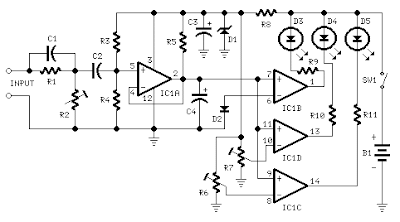
This circuit is intended to indicate the power output level of any audio amplifier. It is simple, portable, and displays three power levels that can be set to any desired value. For a standard HiFi stereo power amplifier like the 25W MosFet Audio Amplifier described in these pages, the power output values suggested are as follows:

D5 illuminates at 2W
D4 illuminates at 12.5W
D3 illuminates at 24.5W


The above values were chosen for easy setup, but other settings are possible.
IC1A is the input buffer, feeding 3 voltage comparators and LEDs drivers by means of a variable dc voltage obtained by R5 and C4 smoothing action. In order to achieve setting stability, the supply of IC1 and trimmers R6 & R7 is reduced and clamped to 5.1V by Zener diode D1.

Parts:
  • R1__________100K 1/4W Resistor
  • R2___________50K 1/2W Trimmer Cermet
  • R3__________330K 1/4W Resistor
  • R4____________1M2 1/4W Resistor
  • R5__________470K 1/4W Resistor
  • R6,R7_______500K 1/2W Trimmers Cermet
  • R8____________1K5 1/4W Resistor
  • R9-R11______470R 1/4W Resistors
  • C1___________47pF 63V Ceramic Capacitor
  • C2__________100nF 63V Polyester Capacitor
  • C3___________47µF 25V Electrolytic Capacitor
  • C4____________1µF 25V Electrolytic Capacitor
  • D1______BZX79C5V1 5.1V 500mW Zener Diode
  • D2_________1N4148 75V 150mA Diode
  • D3-D5________3mm. Yellow LEDs
  • IC1_________LM339 Quad Voltage Comparator IC
  • SW1__________SPST Slider Switch
  • B1_____________9V PP3
  • Clip for 9V PP3 Battery

Notes:

  • The simplest way to connect this circuit to the amplifier output is to use a twisted pair cable terminated with two insulated crocodile clips.
  • Setup is best accomplished with an oscilloscope or an audio millivoltmeter like the one described in these pages. Precision Audio Millivoltmeter
  • A 1KHz sine wave generator with variable output is also required (see a suitable circuit in this website also). 1KHz Sinewave Generator
  • Connect the generator to the amplifier's input and the Audio Power Indicator to the output of the amplifier, in parallel with the oscilloscope probe or the audio millivoltmeter input.
  • When using high power outputs disconnect the loudspeakers to avoid Tweeters damage and connect in their place an 8 Ohm 20-30 Watt wirewound resistor.
  • Remember that VRMS output is equal to output Peak-to-Peak Voltage divided by 2.828.
  • RMS power output in Watts is equal to VRMS2 divided by speaker impedance (usually 8 or 4 Ohm).
  • Example: set the output of the 1KHz sinewave generator to read 14V on the audio millivoltmeter (24.5W @ 8 Ohm). Set R2 until D3 illuminates, and be sure that D3 turns-off when diminishing a little the generator's output.
  • Do the same with R7 for D4 and R6 for D5. The readings of the audio millivoltmeter must be 10V (12.5W @ 8 Ohm) and 4V (2W @ 8 Ohm) respectively.

Six-LED Bar Power Indicator

Useful to monitor audio power delivered to loudspeakers
No power supply - no setup required

This device, connected to the loudspeaker output of an audio amplifier, will indicate the instantaneous output power delivered to the loudspeaker(s) by means of six LEDs illuminating one after another by voltage values increasing little by little, providing the visual impression of a luminous bar or column, increasing and decreasing in height following the increase and decrease of the signal's level.


The input signal is first rectified by D1 and then sent to six different voltage dividers, one for each LED. In this way, the indication provided by the LEDs illumination of this "Power Display", will be related to the instantaneous power sunk by the whole loudspeaker cabinet. Six output power levels are displayed by the LEDs in a 2W - 80W range (no setup required). Each nominal power level indication into 8 Ohms load is reached when the respective LED illuminates at full brightness.

Parts:

  • R1_____________220R 1/2W Resistor
  • R2,R5,R6,R8____100R 1/4W Resistors
  • R10,R12,R14____100R 1/4W Resistors
  • R3_____________220R 1/4W Resistor
  • R4,R7__________330R 1/2W Resistors
  • R9_____________560R 1/2W Resistor
  • R11____________820R 1/2W Resistor
  • R13______________1K2 1/2W Resistor
  • D1___________1N4004 400V 1A Diode
  • D2,D4,D6__BZX79C2V7 2.7V 500mW Zener Diodes
  • D3,D5,D7,D8,D9,D10 Red LEDs (Any dimension and shape) (See Notes)

Notes:

  • The output power indicated by each LED must be doubled when 4 Ohms loads are driven.
  • The circuit can be adapted to suit less powerful amplifiers by reducing the number of LEDs and related voltage dividers.
  • LEDs of any dimension can be used, but rectangular shaped devices will be more suitable to be compacted in bars or columns.
  • For a stereo amplifier, two identical circuits are required.

Tuesday, March 31, 2009

Car Parking Sensor

This circuit was designed as an aid in parking the car near the garage wall when backing up. LED D7 illuminates when bumper-wall distance is about 20 cm., D7+D6 illuminate at about 10 cm. and D7+D6+D5 at about 6 cm. In this manner you are alerted when approaching too close to the wall.

All distances mentioned before can vary, depending on infra-red transmitting and receiving LEDs used and are mostly affected by the color of the reflecting surface. Black surfaces lower greatly the device sensitivity. Obviously, you can use this circuit in other applications like liquids level detection, proximity devices etc.

Circuit operation:

IC1 forms an oscillator driving the infra-red LED by means of 0.8mSec. pulses at 120Hz frequency and about 300mA peak current. D1 & D2 are placed facing the car on the same line, a couple of centimeters apart, on a short breadboard strip fastened to the wall. D2 picks-up the infra-red beam generated by D1 and reflected by the surface placed in front of it. The signal is amplified by IC2A and peak detected by D4 & C4. Diode D3, with R5 & R6, compensates for the forward diode drop of D4. A DC voltage proportional to the distance of the reflecting object and D1 & D2 feeds the inverting inputs of three voltage comparators. These comparators switch on and off the LEDs, referring to voltages at their non-inverting inputs set by the voltage divider resistor chain R7-R10.

Parts List:
  • R1 - 10K 1/4W Resistor
  • R2,R5,R6,R9 - 1K 1/4W Resistors
  • R3 - 33R 1/4W Resistor
  • R4,R11 - 1M 1/4W Resistors
  • R7 - 4K7 1/4W Resistor
  • R8 - 1K5 1/4W Resistor
  • R10,R12-R14 - 1K 1/4W Resistors
  • C1,C4 - 1µF 63V Electrolytic or Polyester Capacitors
  • C2 - 47pF 63V Ceramic Capacitor
  • C3,C5 - 100µF 25V Electrolytic Capacitors
  • D1 - Infra-red LED
  • D2 - Infra-red Photo Diode (see Notes)
  • D3,D4 - 1N4148 75V 150mA Diodes
  • D5-7 - LEDs (Any color and size)
  • IC1 - 555 Timer IC
  • IC2 - LM324 Low Power Quad Op-amp
  • IC3 - 7812 12V 1A Positive voltage regulator IC

Notes:
  • Power supply must be regulated (hence the use of IC3) for precise reference voltages. The circuit can be fed by a commercial wall plug-in adapter, having a DC output voltage in the range 12-24V.
  • Current drawing: LEDs off 40mA; all LEDs on 60mA @ 12V DC supply.
  • The infra-red Photo Diode D2, should be of the type incorporating an optical sunlight filter: these components appear in black plastic cases. Some of them resemble TO92 transistors: in this case, please note that the sensitive surface is the curved, not the flat one.
  • Avoid sun or artificial light hitting directly D1 & D2.
  • If your car has black bumpers, you can line-up the infra-red diodes with the (mostly white) license or number plate.
  • It is wiser to place all the circuitry near the infra-red LEDs in a small box. The 3 signaling LEDs can be placed far from the main box at an height making them well visible by the car driver.
  • The best setup is obtained bringing D2 nearer to D1 (without a reflecting object) until D5 illuminates; then moving it a bit until D5 is clearly off. Usually D1-D2 optimum distance lies in the range 1.5-3 cm.
  • If you are needing a simpler circuit of this kind driving a LED or a relay

Thursday, March 26, 2009

Fluid Level Sensor # 2

This Fluid-Level Sensor circuit uses an AC-sensing signal to eliminate electrolytic corrosion on the probes. The AC signal is rectified and used to drive Transistor T1 that drives the relay. The relay is a 12-V type of your choice.


Transistor T1 can also be a TUP. Check out the TUP/TUN document for a large selection of European transistors and what this system is all about. Diodes D2 and D3 are both small signal diodes (1N4148). Diode D1 (1N4001) eliminates transients and possible sparking over the relay coil. Do not use a signal diode for this but a rectifier diode like the 1N4001 or other types of the 1N400x series. Resistor R2 controls the sensitivity. Also your choice. Select one between 10 and 22 Mega-ohm, or use a trim-pot.

The MC14093B is a CMOS quad 2-input NAND Schmitt trigger. The supply voltage can be between 3.0 and 18Vdc. It is pin-for-pin compatible with the CD4093. The capacitors are standard ceramic types but try others if you have them available. (download schematic)

Parts List:
  • R1 = 470K N1,N2 = MC14093B
  • R2 = 15M* T1 = 2N3906 (these will work also: PN200, 2N4413)
  • C1-C4 = 2N2 (2.2nF) (NTE159, ECG159, BC557, BC157, TUP)
  • D1 = 1N4001 Ry = Relay (12V or matching supply voltage)
  • D2,3 = 1N4148 Sensor = Stainless Steel probes, brass, chrome, etc.

Please note:

Unused inputs MUST be tied to an appropriate voltage level, either ground or +12V. In this case, tie input pins 8, 9, 12, and 13 to either ground or +12v. Unused outputs (10 & 11) MUST be left open. You can use them as spares when needed.
In regards to the sensor, use your imagination. Stainless steel would be preferred but try other materials too. Depending on what type of fluid you use it for you naturally would choose your type of sensor which would resist corrosion for that particular fluid. I often use chrome bicycle spokes with very good success. The 'Sensor' works via the capacitive method.

The "RESET" switch in the circuit is optional. The relay can be replaced with anything you like; buzzer, lamps, other relays, etc.

Below are a couple valuable comments from Dave Burton of Burton Systems Software:

Thanks, Tony, for publishing your Fluid-Level Sensor design. I'm using it to detect sewer line plugs (water backing up toward the access port), and hot water heater / clothes washer / AC condensate pump overflows/leaks (water on the basement floor). It works very well.

Also, it says "the 'Sensor' works via the capacitive method." But I don't think that is correct. It would be more accurate to say that, for detecting fluids that are perfect insulators, the circuit CAN be made to work by detecting an increase in capacitance when the fluid replaces air in an air gap in the sensor.

But for the more common case of fluids that are not perfect insulators (like water on my basement floor), the circuit works by detecting resistive conduction through the fluid. It is lowered resistance that is detected, not increased capacitance.

To detect insulating fluids via the capacitive method would require good sized plates separated by an air gap, and careful adjustment of the sensitivity via R2 to distinguish between the possibly small change in capacitance due to the presence of the fluid. The difference might be small because there is only a fairly small differences between the dielectric constants of air and some common fluids. E.g., air has a dielectric constant of 1, and typical oils have dielectric constants of 2 to 5. Note, too, that desire to get a measurably large amount of capacitance leads us to desire that the gap between the plates be small (because the capacitance is inversely proportional to the distance between the plates), but the gap cannot be too small, lest capillary action hold fluid between the plates even after the fluid level has dropped below our sensor.

But to detect dirty water or tap water you can use almost anything: even a pair of bare wire ends several am apart works just fine.

Also, one handy feature not mentioned in the article is that several resistive "sensors" can be hooked up together (in parallel) to detect fluid at any of several different locations.

Fluid Level Detector

The LM903 uses the thermal-resistive probe technique to measure the level of nonflammable fluids. A low fluid level is indicated by a warning lamp operating in continuous or flashing mode. All supervisory requirements to control the thermal - resistive probe, including short and open circuit probe detection, are incorporated within the device. The circuit has possible applications in the detection of hydraulic fluid, oil level, etc., and may be used with partially conducting fluids.


Circuit Operation

A measurement is initiated when the supply is applied, provided the control input pin 7 is low. Once a measurement is commenced, pin 7 is latched low and the ramp capacitor on pin 12 begins to charge. After 25 ms when switch-on transients have subsided, a constant current is applied to the thermo-resistive probe. The value of probe current, which is supplied by an external PNP transistor, is set by an external resistor across an internally generated 21V reference. The lamp current is applied at the start of probe current.

35 ms after switch-on, the voltage across the probe is sampled and held on external capacitor C1 (leakage current at pin 1 less than 1 nA). After a further 1.5 seconds the difference between the present probe voltage and the initial probe voltage is measured, multiplied by 3 and compared with a reference voltage of 850 mV (externally adjustable via pin 16). If the amplified voltage difference is less than the reference voltage the lamp is switched off, otherwise the lamp commences flashing at 1 Hz to 2 Hz. 10 ms later the measurement latch operates to store the result and after a further 8 ms the probe current is switched off.

A second measurement can only be initiated by interrupting the supply. An external CR can be arranged on pin 7 to prevent a second measurement attempt for 1 minute. The measurement condition stored in the latch will control the lamp.

PROBES

The circuit effectively measures the thermal resistance of the probe. This varies depending on the surrounding medium (Figure 1). It is necessary to be able to heat the probe with the current applied and, for there to be sufficient change in resistance with the temperature change, to provide the voltage to be measured.


Probes require resistance wire with a high resistivity and temperature coefficient. Nickel cobalt alloy resistance wires are available with resistivity of 50 mXcm and temperature coefficient of 3300 ppm which can be made into suitable probes. Wires used in probes for use in liquids must be designed to drain freely to avoid clogging. A possible arrangement is shown in Figure 2.

The probe voltage has to be greater than 0.7V to prevent short circuit probe detection less than 5V to avoid open circuit detection. With a 200 mA probe current this gives a probe resistance range of 4X to 25X. This low value makes it possible to use the probe in partially conducting fluids.

Using resistance wire of 50 mXcm resistivity, 8 cm of 0.08 mm (40 AWG) give approximately 8X at 25ßC. Such a probe will give about 500 mV change between first and second measurements in air, and 100 mV change with oil, hydraulic fluid, etc., in the application circuit. With an alarm threshold of 280 mV (typ) lack of fluid can readily be detected. As the probe current, measurement reference and measurement period are all externally adjustable, there is freedom to use different probes and fluids.

Another possibility is the use of high temperature coefficient resistors made for special applications and positive temperature coefficient thermistors. The encapsulation must have a sufficiently low thermal resistance so as not to mask the change due to the different surrounding mediums, and the thermal time constant must be quick enough to enable the temperature change to take place between the two measurements. The ramp timing could be adjusted to assist this. Probes in liquids must be able to drain freely.


I2C Temperature Sensor

The electronic circuit is Temperature Sensor with I2C program. It is a circuit that plugs into the link port of a TI-85, TI-83, or TI-92 calculator and displays the temperature on the screen. Currently, there is only software for the TI-85, but I plan to write some for the TI-92 also. The sensor circuit draws power from the link port, so there is no need for any external batteries. The overall size of the unit will depend on the size you make it. Mine is about .75" by .5".


Parts

  • Two small switching diodes. I think that just about any kind will work.
  • I used 1N914 ones.
  • One small electrolytic capacitor. I tried 2.2uF, 10uF, and 100uF, and all of them worked.
  • An LM75CIM-5 integrated circuit (IC) made by National Semiconductor. For a more detailed description, you can read the data sheets on it onNational's WEB page at www.national.com and also check theirdistributors. It is a surface mount chip, so it is pretty hard to workwith.
  • A 2.5mm stereo plug and cord. You can buy one, but I just cut a calculator link in half.
  • A kit that allows you to etch your own boards. You can buy these at Radio Shack for about $15 and they can be used more than once. You canalso use another method, but I found this to be the cheapest for workingwith surface mount devices.
  • Construction Materials. Just general things like a soldering iron,solder, etc.

Directions

  1. Come up with some way of using the surface mount IC. I etched my own PCB for it.
  2. Solder all the parts for the circuit on the board or however you chose to make the circuit. Be sure to follow the schematic for this step. And make sure the red and white wires are connected correctly accordingto the schematic. The only part you don't have to follow is how youconnect the A0-A2 pins. You can find out what pins these are in the data sheets available on National's WEB page www.national.com read the next couple sections of these plans. If you connect them differently, you will have to change the chip ID which is explained below.

Software

The software I wrote to control the I2C Temperature Sensor is very simple to understand. Simply run the ZShell program and it will display the temperature on the screen in both Celcius and Farenheit. If an error message appears on the screen, this section will help you.

The program continuously updates the temperature about twice every second. To exit the program, simply press [EXIT]. There is also a feature that can be activated by pressing [F5]. This will allow you to change the chip ID that is set by the A0 to A2 pins on the IC. If this is set wrong, it will display an error on the screen. After pressing [F5], you can change the ID number by pressing [UP] and [DOWN]. Then, simply press [ENTER] and it will bring you back into the program. This also allows you to have up to 8 chips in the same circuit if you change around the circuit a little bit and give each one a separate chip ID set by the A0 to A2 pins. If changing the chip ID does not get rid of the error, make sure the plug is plugged into the calculator all of the way. If the error is still there, check over your construction of the circuit. If you have an error and change something external, either plugging in the cord or fixing something on the circuit, be sure to restart the program or alter the chip ID to restart the program.

Oxygen Sensor Simulator


The oxygen sensor simulator as built on a protoboard. Note the cigarette lighter plug used for power source. The adjustment knob is at the left, and the switch is on the right. The red indicator LED is in the middle. Only use red, because the voltage drop of the LED is part of the circuit!


The schematic diagram for the simulator. Closing the switch engages the simulator. Turning the knob clockwise simulates a lean condition, turns the LED off, and the car should start running rich to compensate. The big "V" is a digital voltmeter(not shown in the pictures). Using a smaller value for C1, perhaps 4.7 uF, will make the circuit oscillate faster and might be more like a real oxygen sensor(a new sensor switches more often than an old one).


The adapter cable. Note the connector recycled from an old oxygen sensor. Hard to see under the black tape: 100K resistor.

The schematic diagram of the adapter cable and oxygen sensor. Note the heater is shown as a resistor, mine measured about 7 ohms.

RF Sensing Alarm


RF sensing alarm is a device that would alert when it detects a continuous RF transmission that lasts more than 5 minutes. The device would have to be broadband (HF/VHF/UHF), be sensitive enough to detect a 5W transmission from inside the shack using a telescopic antenna, and produce a sound loud enough to alert me anywhere in the house.

The RF sensing alarm would also have to be self-contained, which means without any hookups to my radios. After a bit of reading and thinking, I came up with a solution that meets all the initial objectives. Here's circuit in detail.


The circuit shown above may look scary for some of you, but it is not. It can be broken down into four stages. Let's look at them one at a time. The first stage acts as a RF sensor circuit. It is made of U1C, one of the four operational amplifiers of a LM324 chip, and its associated input circuitry. U1C is used as a voltage comparator. Note that the two U1C inputs (plus and minus) have similar DC circuits connected to them. The plus input has R7, R8 and D3, and the minus input has R6, R10 and D5. In these two circuits, D3 and D4 are partly biased (about 200 mV of forward voltage) in order to better exploit the variation of voltage versus current that the diode produces. This translates into increased RF sensitivity.

In an idle condition (no RF detected), potentiometer R10 is set to make the voltage at the minus input of U1C slightly lower then the one at its plus input. This keeps the output of comparator U1C saturated to the "high" state (near supply V+). A strong RF signal present at the antenna terminal J1 reaches D3, a schottky diode, through C3, a coupling capacitor. The diode rectifies this signal and generates a drop of voltage at D3 anode. This makes the voltage at the plus input of U1C fall below the one set at the minus input. As a result, the output of comparator U1C flips down to the "low" state (near ground). In this state, the circuit is in RF detection mode and timer U1B is activated. Note that as soon as the RF signal disappears, the comparator immediately returns to its high state, resetting the entire alarm circuit. Ferrite bead FB1 and resistor R8 are used to block the RF from reaching comparator U1C. Additional RF decoupling is provided by capacitors C2 and C5.

The second stage acts as a timer. It is made of U1B, D4, C4 and R9. U1B is again used as a voltage comparator. When no RF is detected, capacitor C4 is kept charged by the "high" state of U1C. When RF is detected by the first stage, capacitor C4 is left "floating" and starts to slowly discharge through R9. When C4 is sufficiently discharged, after approximately 5 minutes, the voltage at the plus input of U1B falls below the one at the minus input which is set by D5 (about 200 mVDC). As a result, the output of comparator U1C flips down to the "low" state (near ground). In this state, the alarm is tripped. The timer stage drives piezo oscillator U1A and PNP transistor Q1. The latter is added to drive an external device with a voltage close to V+ when the alarm is tripped. The two diodes in series with the emitter provide a drop of voltage so that the base-emitter junction of Q1 is not biased when U1B output is in "high" state. The 2N3906 or equivalent transistor will safely supply a current of up to 50 mA.

The third stage is an astable multivibrator (square wave oscillator) and is made of U1A and surrounding components. It drives the piezo vibrator to produce a loud high-pitch sound. The oscillator circuit will operate only when the output of U1B presents a "low" state. Diode D2 serves as an isolating device between the two stages when U1B is in "low" state. The oscillator's frequency is set by capacitor C1 and resistor R5. The values chosen make the circuit oscillate at approximately 2600 Hz, a frequency that causes the piezo to generate the loudest sound.

The last stage is a simple buffer U1D that sinks current to turn on LED D1 whenever a RF signal is sensed by U1C. R1 limits the current to a safe level for the buffer, less than 20 mA.

The balanced input configuration of comparator U1C allows the supply voltage V+ to vary over a wide range and the entire circuit will still work. I designed the circuit for a 13.8 V supply, but I verified that the circuit works down to approximately 10 V without recalibrating it, and down to approximately 5 V if recalibrated. The high end of the range is more delicate to set since devices such as the LED, the piezo vibrator and polarized capacitors may be overstressed if component value changes are not made. Consequently, I would not recommend going beyond 20 V.

Part Lists

C1 ------ .01uF, ceramic
C2 ------ 1000pF, ceramic
C3 ------ 1000pF, ceramic
C5 ------ 1000pF, ceramic
C4 ------ 100uF, 25V, tantalum or electrolytic (see text)
C6 ------ 10uF, 25V tantalum or electrolytic
C7 ------ .1uF, ceramic
D1 ------ LED, any color
D2 ------ 1N4148 or equiv.
D3 ------ 1N5711, schottky
D4 ------ 1N4148 or equiv.
D5 ------ 1N5711, schottky
D6 ------ 1N4148 or equiv.
D7 ------ 1N4148 or equiv.
FB1 ------ Ferrite bead
J1 ------ BNC, Female panel mount
Q1 ------ 2N3906, PNP or equiv.
R1 ------ 100K
R2 ------ 100K
R4 ------ 100K
R3 ------ 1K
R5 ------ 10K
R6 ------ 1M
R7 ------ 1M
R8 ------ 27k
R9 ------ 470K
R10 ------ 50K, 10-turn pot., Bourns 3006 type
R11 ------ 22K
U1 ------ LM324 Quad Op. Amp.
X1 ------ Piezo, muRata PKM-11 or Radio Shack 273-73 or equiv. External drive type.
Socket --- 14-pin DIP
Coax --- Short piece of RG-174 or equiv.
Box --- Hammond 1591A suggested
Ant --- Right-angle BNC, telescopic

This project is relatively inexpensive to assemble. If all the components are purchased, it should cost less than $25 to build it. Obviously, your junkbox's size will dictate the cost. I re-used components taken from old PCBs. This allowed me to build the project for less than five dollars, including PCB and box.

I admit, it is a rather compact design. The intent here is to make the design fit in a very common Hammond 1591A plastic box. Note that the circuit can be assembled using other techniques: universal PCB, veroboard, deadbug, wire-wrap and even a combination of these techniques. The layout is not critical except for the RF portion of the circuit: Components D3, C3, FB1 and R8 should be mounted as close of possible to each other using very short leads. This will guarantee proper operation up into the UHF spectrum. Also, decoupling capacitors C2 and C5 should be mounted as close as possible to pins 9 and 10 of U1C.

When assembling the PCB, use a soldering iron with a fine tip. Start by installing the LM324 IC. This is the hardest component to solder because of the pin spacing and overall PCB component density. An IC socket is desirable since the LM324 is rather sensitive to pin shorting compared to other operational amplifiers I've used in the past. With a socket, replacing it is a snap. Make sure you solder all components on the two PCB sides. Many component leads are used as vias to jump from top to bottom layers. Soldering all components this way guarantees you a functional circuit at the end. It's happened to me too often to forget to solder a component on the component side of the PCB.

Ferrite bead FB1 is inserted over a short piece of solid wire and the wire is soldered to the PCB pads. Potentiometer R10 is located on the PCB edge so that its adjustment screw can be accessed through a small hole drilled on one of the faces of the box. I've chosen not to put connectors for external connections to the LED, the piezo vibrator, supply line and the auxiliary output. Solder small gauge (#26 or smaller) wires directly to the PCB pads and connect the other ends to the external devices.

For antenna connection, I recommend using a female panel-mount BNC connector. It is small, reliable and will accept most right-angled telescopic antennas when mounted horizontally. Other RF connectors can be used if desired. Since the input impedance of the circuit is quite high, maintaining a constant impedance through the connectors is not an issue. In general though, it is good practice to avoid using UHF connectors (PL-259/SO-239) when working above 200 MHz, since they are not of constant impedance type. For coaxial cable, a short piece of RG-174 type or equivalent is preferred to limit overstressing of the PCB pads. This type of coax is much easier to route in a small box anyway. Solder the bare ends directly to the pads.